
Pressure pad device for pressure machinery

A pressure pad and mechanical technology, applied in the direction of presses, fluid pressure actuators, mechanical equipment, etc., can solve the problems of high cost of pits, high production costs, heavy economic burdens on enterprises, etc., to reduce gas source consumption , save manufacturing cost, reduce the effect of using cost

Inactive Publication Date: 2014-04-30
镇江市锻压机床厂
View PDF6 Cites 2 Cited by
  • Summary
  • Abstract
  • Description
  • Claims
  • Application Information

AI Technical Summary

Problems solved by technology

For example, for a press of about 400 tons, the pit is generally more than 5 meters, and the cost of the pit remains high, which brings a heavy economic burden to the enterprise.
[0003] In addition, the stroke height of the pressure pad generally needs to be adjustable, and an additional stroke adjustment mechanism needs to be installed, and the production cost is relatively high.

Method used


Image

  • Pressure pad device for pressure machinery

Examples


Embodiment Construction

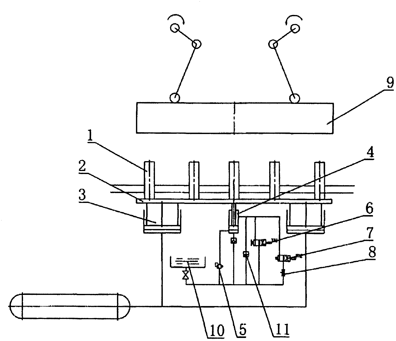
[0010] As shown in the figure, a pressure pad device of a press machine includes a ejector rod supporting plate 2 on which a ejector rod 1 is installed, and a slider 9 is arranged on the top of the ejector rod 1 to cooperate with it for pressing and forming a workpiece. The slider 9 is connected by a crank The rod mechanism drives to do periodic upward and downward movements.

[0011] It also includes a cylinder 3 with a power source and a hydraulic cylinder 4 without a power source. There are two cylinders 3, which are fixed on both sides of the lower end surface of the ejector rod support plate 2. The cylinder 3 is connected with the air compressor air storage tank through a gas pipe.

[0012] The hydraulic cylinder 4 is arranged between the two cylinders 3, and its piston rod is fixedly connected with the ejector support plate 2. The rod chamber and the rodless chamber of the hydraulic cylinder 4 are respectively connected to the oil tank 10 through the oil pipe, and the oil...


PUM


Abstract

The invention discloses a pressure pad device for pressure machinery. The pressure pad device for pressure machinery comprises an ejection rod supporting plate provided with an ejection rod, an air cylinder provided with a power source, and a hydraulic oil cylinder without a power source, wherein the air cylinder provided with the power source and the hydraulic oil cylinder without the power source are fixedly connected with the ejection rod supporting plate; the rod cavity and the rodless cavity of the hydraulic oil cylinder are connected with an oil tank by an oil tube respectively, and a liquid-filling valve is installed on the oil tube; the rodless cavity of the hydraulic oil cylinder is connected with a boost oil circuit, an overflow valve is installed on the boost oil circuit, and the rod cavity is connected with an unloading oil circuit. After a slide block moves downwards to press the ejection rod, the boost oil circuit of the hydraulic oil cylinder is used for boosting, and cooperated with the air cylinder to achieve requirements on a rated pressure, and the air cylinder does not need to be designed into a multi-stage air cylinder with a large volume, meanwhile, the consumption of an air source is reduced, and then the use cost of users is greatly reduced; after the slide block moves upwards, the unloading loop of the hydraulic oil cylinder is used for performing locking, rapid unloading and slow unloading respectively according to process requirements, thus the ejection rod is static at first, and then rapidly moves upwards, and slowly moves upwards while approaching to an upper dead centre, thus reducing impact and noise.

Description

technical field [0001] The invention relates to a press machine pressure pad device, in particular to a press machine pressure pad device with compact structure and energy saving. Background technique [0002] The pressure pad is used to play the role of edge and unloading during deep drawing, and as the top piece during punching. The current pressure pad is all pneumatic, which is composed of an air storage tank connected to a cylinder. In order to achieve the rated tonnage, the cylinder of the air cushion is used Into a multi-stage cylinder, bulky. In the process, the pressure pad is required not to rise and reset immediately with the slider, but to reset after a period of delay to avoid deformation of the workpiece. This function is called the pressure point locking function. In order to realize the locking function, additional locking components need to be connected to the multi-stage cylinder, which further increases the volume. The general press workbench is buried b...

Claims


Application Information

Patent Timeline
Patent Type & Authority Applications(China)
IPC IPC(8): B30B15/00F15B13/04
Inventor 鲍荣龙
Owner 镇江市锻压机床厂
Learn More