Damping control method for existing frame structure

A frame structure and control method technology, applied in the direction of earthquake resistance, building components, etc., can solve the problems of high device cost and difficult construction, and achieve the effects of low cost, simple construction, and reduced earthquake response

Inactive Publication Date: 2014-07-16
BEIJING JIAOTONG UNIV
View PDF7 Cites 0 Cited by
  • Summary
  • Abstract
  • Description
  • Claims
  • Application Information

AI Technical Summary

Problems solved by technology

[0004] The above-mentioned indirect reinforcement method, shock absorption control method and the devices used are expensive and difficult to construct, and are usually used in major buildings, but not commonly used in general frame structures

Method used


Image

  • Damping control method for existing frame structure
  • Damping control method for existing frame structure

Examples


Embodiment 1

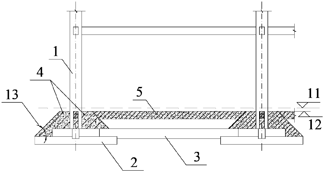
[0026] refer to figure 1 , the height from the ground floor of a frame structure to the top of the first-floor roof is 3.6m, the embedment depth of the independent foundation 2 is 1.5m, the height of the independent foundation 2 is 0.5m, and the top surface of the independent foundation 2 is flush with the top surface of the foundation beam 3 , the floor height of the bottom frame is taken from the top surface of the foundation to the top surface of the first floor, which is 4.6m. Now the seismic response of the frame structure is alleviated by using the damping control method of the present invention. The main steps are as follows:

[0027] Step a, excavate the construction operation space at the indoor floor position of the frame structure, and roughen the surface concrete of the frame column 1 below the indoor floor;

[0028] Step b, setting concrete wing wall 4 on the independent foundation 2 of the frame structure, the thickness is 200mm, and the concrete strength level i...

Embodiment 2

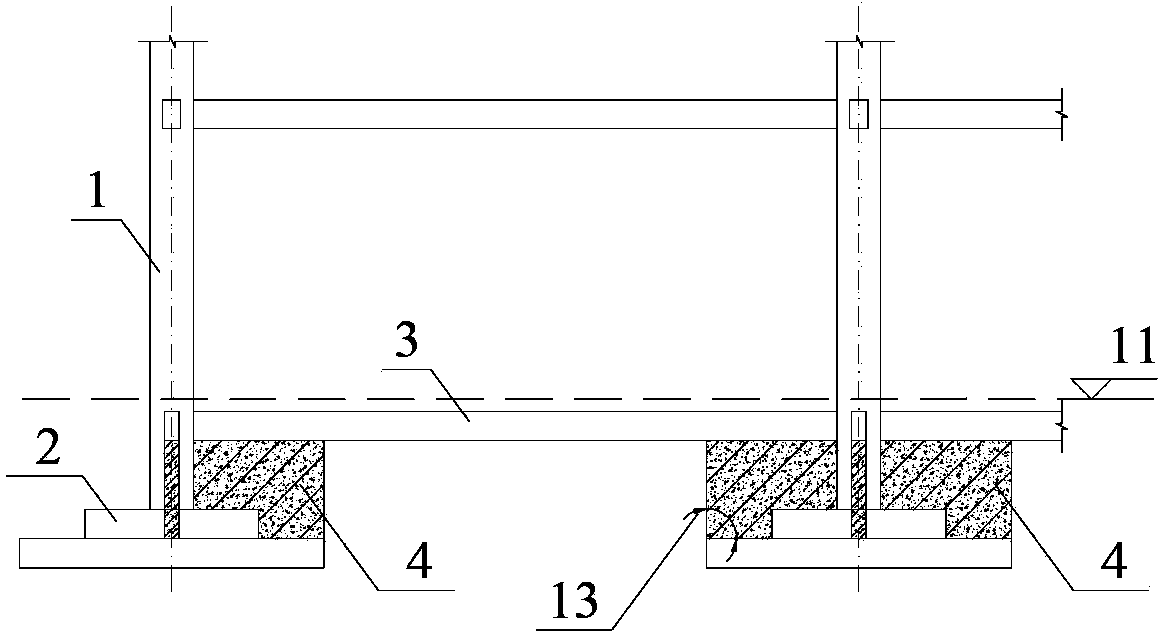
[0032] refer to figure 2 , shows the schematic elevation of the method of the present invention used in the second embodiment of the frame structure. The difference between the frame structure of this embodiment and the first embodiment is that the foundation beam is separated from the independent foundation, and the top surface of the foundation beam is located 50 mm below the indoor floor level. The main construction steps are as follows:

[0033] Step a, excavate the construction operation space at the indoor floor of the frame structure, expose the independent foundation 2 and the foundation beam 3, chisel the surface concrete of the frame column 1 below the indoor floor, and place the foundation beam 3 within the scope of the independent foundation Concrete roughening on the lower surface of the beam;

[0034] In step b, a concrete wing wall 4 is set between the independent foundation 2 and the foundation beam 3, the thickness is 200mm, and the concrete strength level ...


PUM


Abstract

The invention relates to the technical field of building structure damping control, particularly to a damping control method for an existing frame structure. According to the method, concrete wing walls from the top of an isolated foundation to the position lower than the elevation of indoor grade is arranged on the isolated foundation of the frame structure, and a concrete coupling beam is arranged between the tops of the adjacent concrete wing walls; or concrete wing walls are arranged on the isolated foundation and between the isolated foundation and the foundation beam. Through adopting the method of additionally arranging the concrete wing walls and the concrete coupling beam, the build-in position of the frame structure is lifted from the original top surface of the isolated foundation to the top surfaces of the concrete wing walls, the calculation story height of the bottom layer of the frame is reduced, the earthquake action borne by the existing frame structure is effectively reduced, the arrangement of reinforcement for main side force resisting members such as frame beams and frame pillars is reduced, and the benefits of indirectly reinforcing the frame structure are achieved.

Description

technical field [0001] The invention relates to the technical field of damping control of building structures, in particular to a damping control method for an existing frame structure. Background technique [0002] When the frame structure changes the use function, increases the load or increases the floor, it is necessary to carry out seismic reinforcement design or shock absorption control design for the frame structure. The reinforcement method of frame structure can be divided into direct reinforcement method and indirect reinforcement method. Direct reinforcement method is a method of directly adopting seismic reinforcement to structural members, for example, enlarging section method, external bonded section steel method, external bonded steel plate method or external bonded fiber sheet method, etc. The indirect reinforcement method is to change the type of structural system by adding seismic components, for example, by adding seismic walls to change the frame from a ...

Claims


Application Information

Patent Timeline
Patent Type & Authority Patents(China)
IPC IPC(8): E04B1/98
Inventor 袁泉郭猛常鹏孙静贾英杰
Owner BEIJING JIAOTONG UNIV
Why Eureka
Try Eureka