Hose bundle

A hose and annular tube technology, applied in the field of hose bundles, can solve the problems of not being able to use multiple times, not being able to adjust the tightness of the tube bundle, and easy deformation of the tube bundle, and achieve the effects of not being easily deformed, elastically adjustable, and easy to disassemble

Active Publication Date: 2012-10-03
南通嘉立德机电科技有限公司
View PDF5 Cites 16 Cited by
  • Summary
  • Abstract
  • Description
  • Claims
  • Application Information

AI Technical Summary

Problems solved by technology

[0002] At present, most hose bundles are fastened with screws. The disadvantage is that tools are needed to assemble or disassemble, and the tightness of the bundle cannot be adjusted; Apply force to the tube bundle as a whole to disassemble it. This disassembly method makes the tube bundle easy to deform and cannot be used multiple times.

Method used


Image

  • Hose bundle
  • Hose bundle
  • Hose bundle

Examples


Embodiment 1

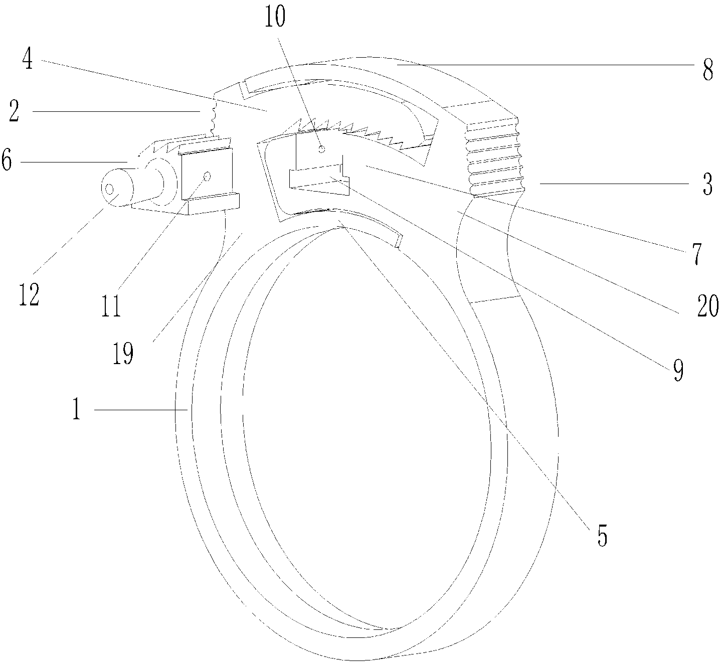
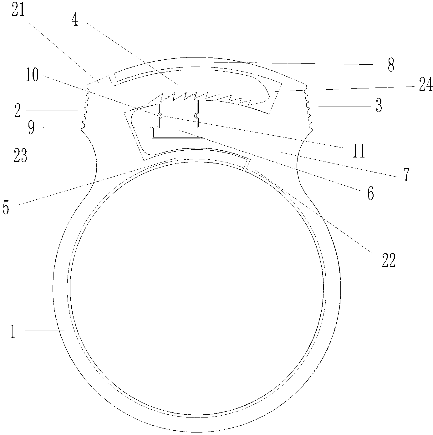
[0017] Such as figure 1 , figure 2 As shown, the hose bundle includes an annular pipe collar 1 with an open end and an interlocking part I 2 and an interlocking part II 3 that cooperate with each other;

[0018] Interlocking part I comprises auxiliary part I19, ratchet bar 4 and protruding ring I5, and ratchet bar and protruding ring I are fixed on one end of annular pipe hoop by auxiliary part I; Ratchet bar and protruding ring I are mutually parallel and keep setting A fixed gap I 23; the convex ring I is below, the ratchet bar is above, the ratchet of the ratchet bar is located on the lower surface, and the ratchet is facing the auxiliary part I;

[0019] Interlock part II includes protruding ring II 8, perforated protruding ring 7, locking piece 6 and auxiliary part II 20, protruding ring II and perforated protruding ring are fixed on the other end of the ring pipe collar through auxiliary part II; protruding ring II and perforated protruding ring are mutually Parallel ...

Embodiment 2

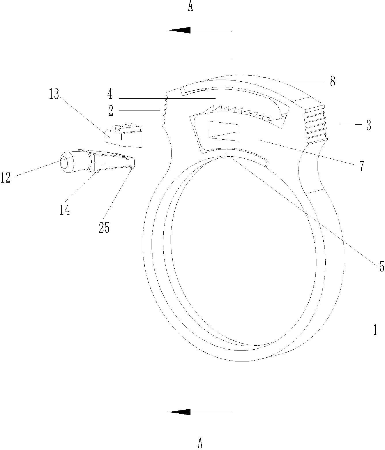
[0027] The difference between this embodiment and Embodiment 1 lies in the hole protruding ring and the interlocking piece.

[0028] Such as image 3 and Figure 4 As shown, the interlocking part is composed of a ratchet part 13 and a push-pull part 14. The push-pull part is wedge-shaped, and its thick end is connected to the handle; the lower end surface of the ratchet part matches its upper end surface;

[0029] The installation hole in the perforated convex ring is composed of an axial installation hole 15 and a radial installation hole 16, the axial installation hole communicates with the radial installation hole, the axial installation hole cooperates with the push-pull part, and the radial installation hole cooperates with the ratchet part ;

[0030] A protruding part 25 is respectively arranged under the thick end and the thin end of the push-pull part, and they play the role similar to the convex point and the concave point in the first embodiment.

[0031] The oper...


PUM


Abstract

The invention discloses a hose bundle which comprises an annular pipe hoop with an opening at the tail end, and mutually matched interlock component I and an interlock component II, wherein the interlock component I comprises an auxiliary component I, a ratchet bar and a convex ring I; the ratchet bar and the convex ring I are mutually parallel and kept at a set gap I; the convex ring I is at the lower part and the ratchet bar is at the upper part; a ratchet is toward the auxiliary component I; the interlock component II comprises a convex ring II, an open pore convex ring, a lock element and an auxiliary component II; the convex ring II and the open pore convex ring are mutually parallel and kept at a set gap II; the convex ring II is at the upper part; the open pore convex ring is at the lower part; the open pore convex ring is matched with the gap I; the ratchet bar is matched with the gap II; a mounting hole matched with the lock element is arranged on the open pore convex ring in an axial direction; and the gap II is communicated with the mounting hole, and the ratchet matched with the ratchet bar is arranged at the upper end of the lock element. The hose bundle disclosed by the invention is convenient to dismantle and mount, adjustable in tightness and not easy to deform.

Description

technical field [0001] The invention relates to a clamp for hoses, in particular to a hose bundle. Background technique [0002] At present, most hose bundles are fastened with screws. The disadvantage is that tools are needed to assemble or disassemble, and the tightness of the bundle cannot be adjusted; Disassemble by applying force to the tube bundle as a whole. This method of disassembly makes the tube bundle easily deformed and cannot be used multiple times. Contents of the invention [0003] The object of the present invention is to overcome the above disadvantages and provide a hose bundle that is easy to disassemble, adjustable in tightness and not easily deformed. [0004] A hose bundle, comprising an annular pipe collar with an open end and interlocking part I and interlocking part II which cooperate with each other in two parts; [0005] The interlocking part I includes an auxiliary part I, a ratchet bar and a protruding ring I, and the ratchet bar and the pro...

Claims


Application Information

Patent Timeline
Patent Type & Authority Applications(China)
IPC IPC(8): F16B2/20
Inventor 陈校波
Owner 南通嘉立德机电科技有限公司
Why Eureka
Try Eureka