Air-boosting hydraulically driven clutch execution mechanism

A technology for actuators and clutches, applied in the direction of fluid-driven clutches, non-mechanical-driven clutches, clutches, etc., can solve the problems of long system response time, incomplete clutch separation, low transmission efficiency, etc., to improve accuracy and response speed, The effect of improving field survivability and good quality control

Active Publication Date: 2012-10-03
BEIJING INSTITUTE OF TECHNOLOGYGY
View PDF6 Cites 20 Cited by
  • Summary
  • Abstract
  • Description
  • Claims
  • Application Information

AI Technical Summary

Problems solved by technology

[0003] At present, the clutch control system of heavy-duty vehicles still widely adopts the control mo

Method used


Image

  • Air-boosting hydraulically driven clutch execution mechanism
  • Air-boosting hydraulically driven clutch execution mechanism

Examples


Embodiment Construction

[0017] Specific embodiments of the present invention will be described in detail below with reference to the accompanying drawings.

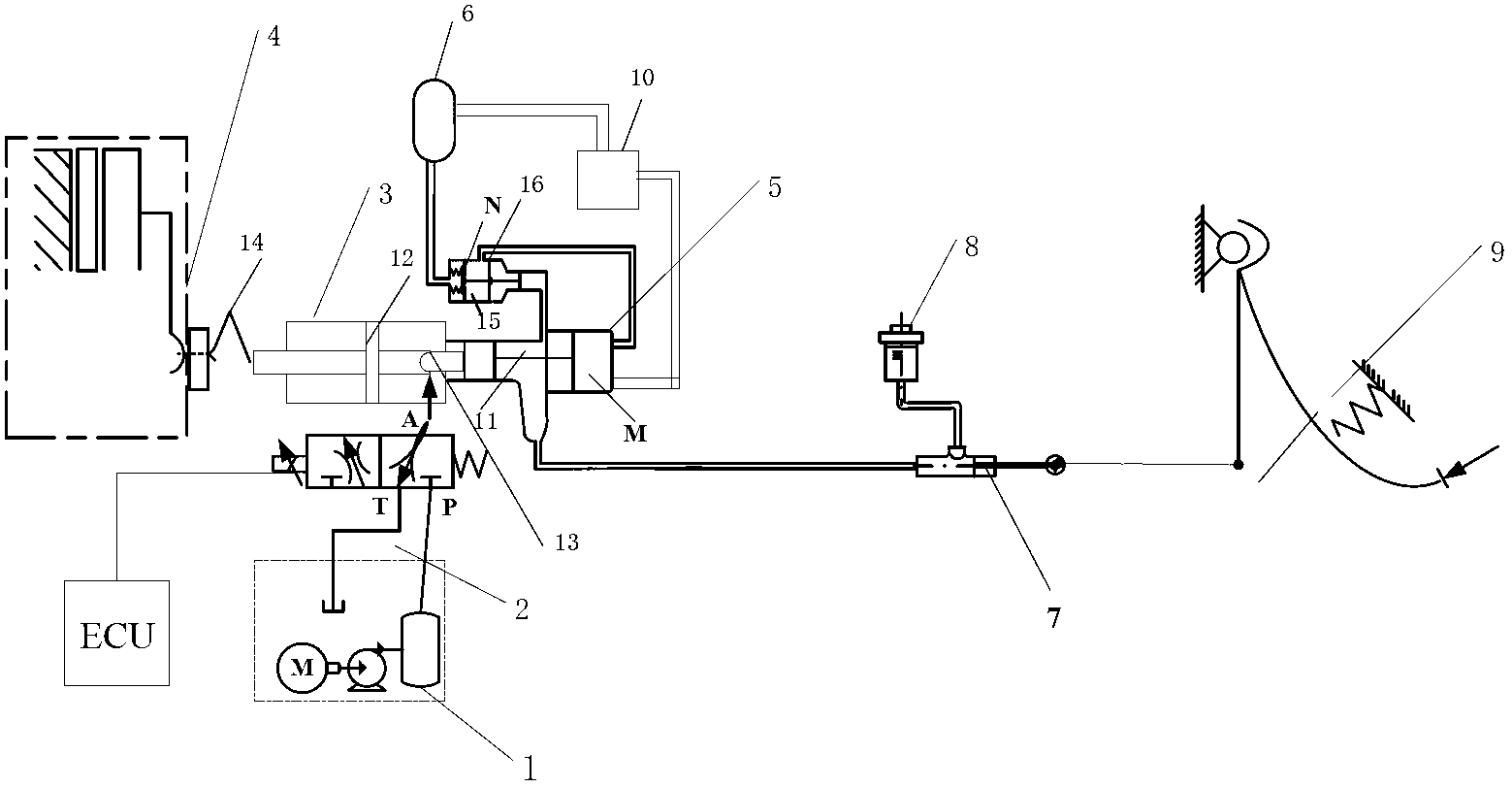
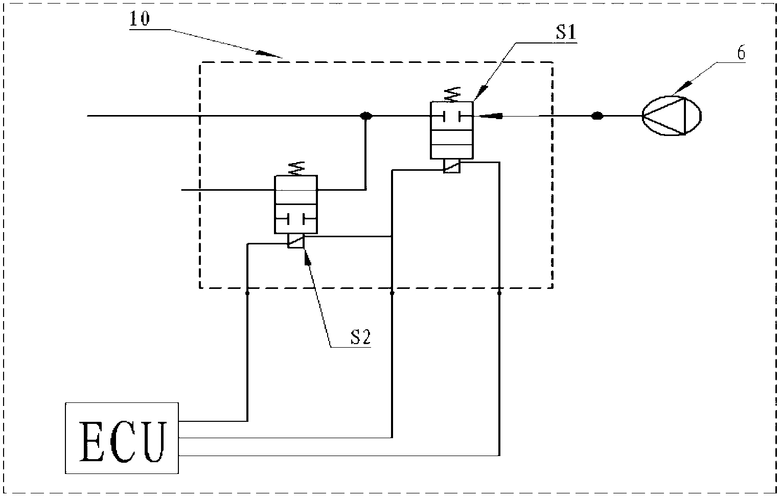
[0018] see figure 1 , the present invention provides a gas-assisted hydraulically driven clutch actuator, including a clutch automatic operating system and a clutch emergency system, wherein the clutch automatic operating system includes a hydraulic oil source 1, a proportional flow valve 2, a hydraulic working cylinder 3, a clutch 4, a clutch point Pump 5, air storage tank 6, air valve block 10, sub-pump working chamber 11, working cylinder piston 12, sub-pump ejector rod 13, separation shift fork 14, sub-pump right chamber M, sub-pump air valve N, of which hydraulic oil Source 1 is the oil source of the entire system, providing high-pressure hydraulic oil for the hydraulic working cylinder 3. The oil outlet of the hydraulic oil source 1 is connected to the oil inlet of the proportional flow valve 2 through the oil pipe, and the oil return port...


PUM


Abstract

The invention discloses an air-boosting hydraulically driven clutch execution mechanism. The air-boosting hydraulically driven clutch execution mechanism comprises a clutch automatic operating system, and is characterized in that the clutch automatic operating system comprises a hydraulic oil source (1), a proportional flow valve (2), a hydraulic operating cylinder (3), a clutch (4), a clutch slave cylinder (5), an air storage tank (6), an air valve block (10), a slave cylinder working chamber (11), an operating cylinder piston (12), a slave cylinder post rod (13), a release fork (14), a slave cylinder right chamber M, a slave cylinder air valve N and an electronic control unit (ECU).

Description

technical field [0001] The invention relates to a clutch actuator, in particular to an air-assisted hydraulic drive clutch actuator. Background technique [0002] With the rapid growth of car ownership and the large increase of non-professional drivers, automatic transmissions for cars are showing a trend of rapid development. There are four types of automatic transmissions for automobiles: hydromechanical automatic transmission (AT), continuously variable transmission (CVT), dual clutch automatic transmission (DCT), and electromechanical automatic transmission (AMT). Among them, the electromechanical automatic transmission is based on the traditional manual transmission and dry clutch, using electronic technology and automatic transmission control theory, an electronic control unit (ECU) as the core, through the actuator to control the separation and engagement of the clutch, transmission The selected gear shifting operation is used to realize the starting and shifting ope...

Claims


Application Information

Patent Timeline
IPC IPC(8): F16D25/08F16D48/04
Inventor 席军强黄星海刘海鸥杨爱均陈慧岩
Owner BEIJING INSTITUTE OF TECHNOLOGYGY
Why Eureka
Try Eureka