Improved structure of oil pressure buffer

A technology of oil pressure buffer and internal pressure, applied in the direction of shock absorber, shock absorber, liquid shock absorber, etc., can solve the problems such as the force hindering the recovery and the uneven buffer effect, so as to reduce the maintenance amount and prolong the use. effect of life

Inactive Publication Date: 2012-10-03
宁波科赛特气动科技有限公司
View PDF0 Cites 5 Cited by
  • Summary
  • Abstract
  • Description
  • Claims
  • Application Information

AI Technical Summary

Problems solved by technology

However, the oil hole on the internal pressure cylinder of the shock absorber used in the current technology prevents hydraulic oil from entering the rear of the piston through the oil hole. The force hindering the recovery is limited, and the buffering effect is not stable.

Method used


Image

  • Improved structure of oil pressure buffer
  • Improved structure of oil pressure buffer
  • Improved structure of oil pressure buffer

Examples


Embodiment Construction

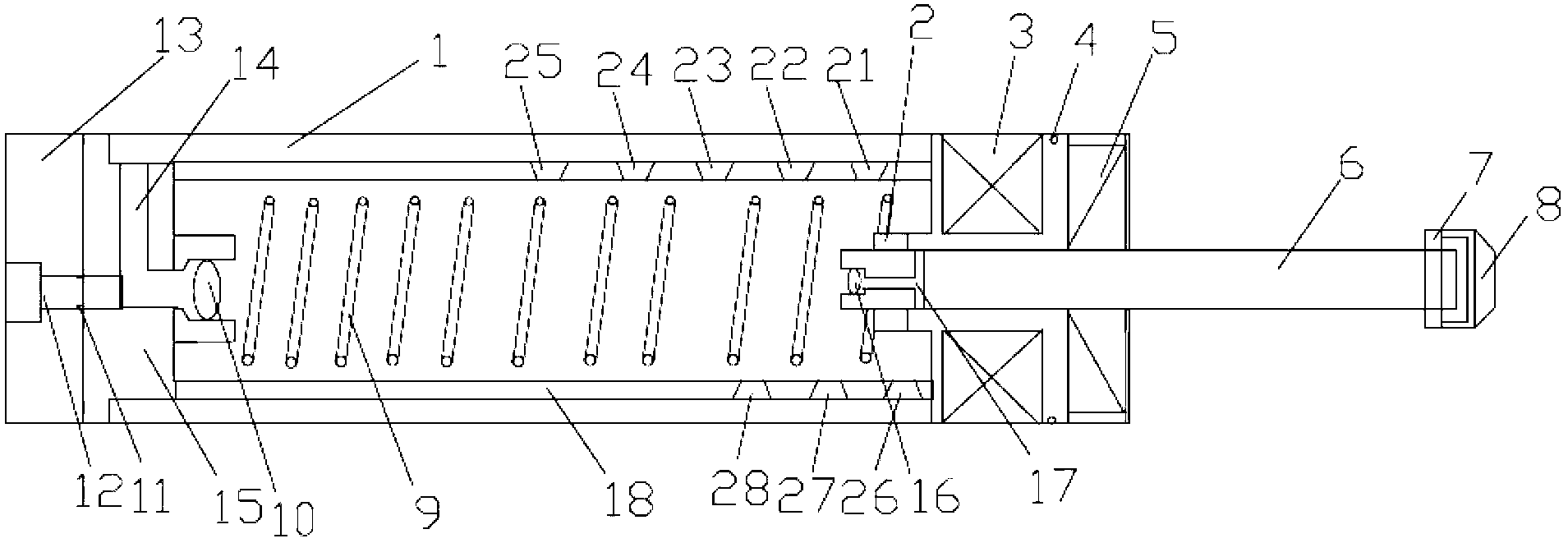
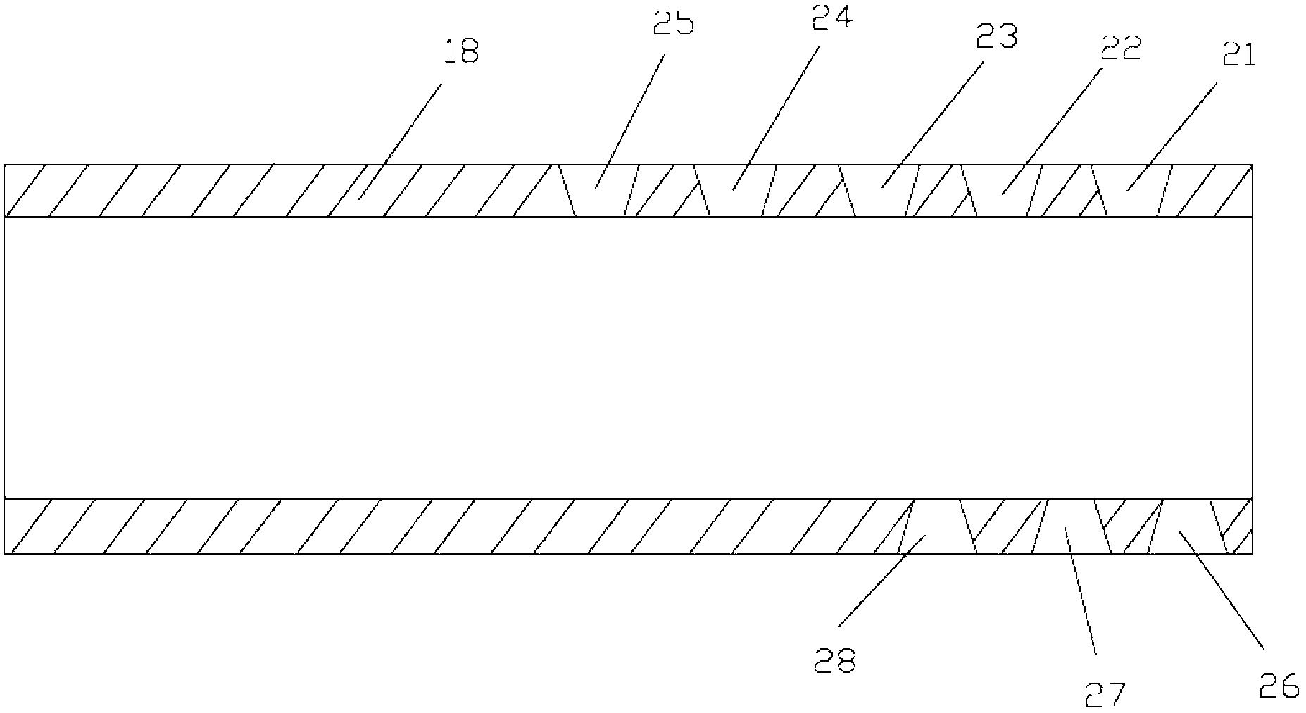
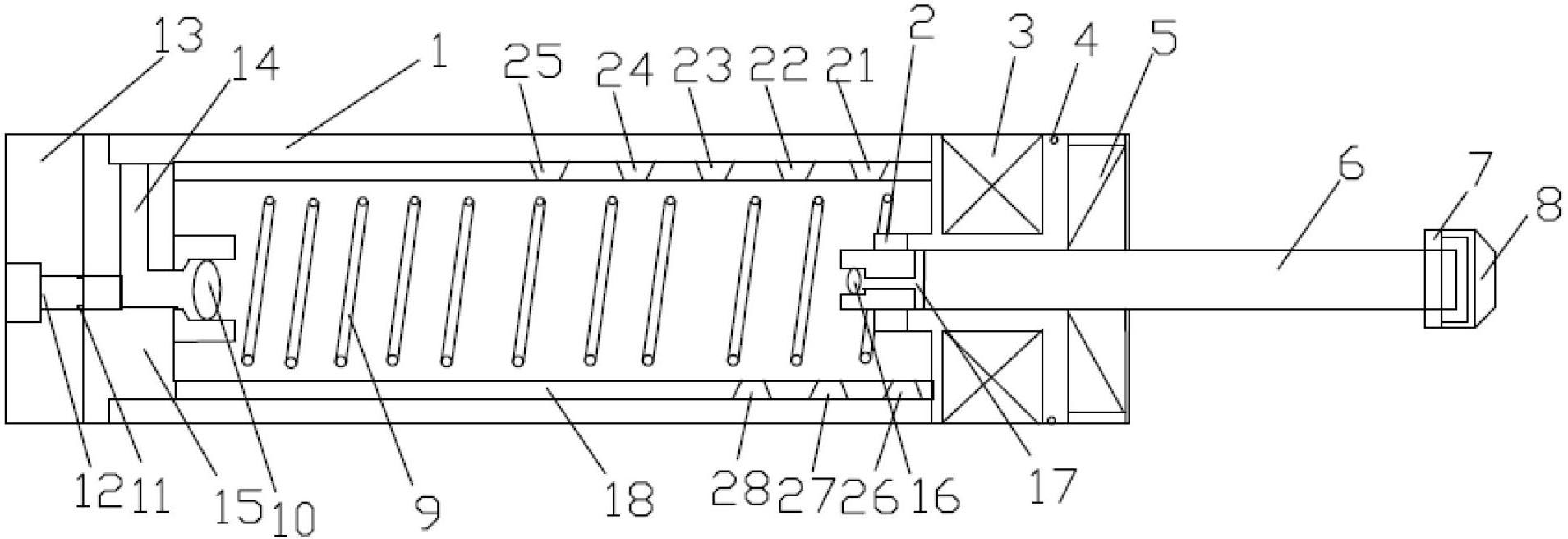
[0027] The specific technical solutions of the present invention will be described in detail below in conjunction with the accompanying drawings. The specific embodiments of the present invention are only exemplary, and can only be used to explain the present invention rather than limit the present invention.

[0028] Such as Figure 1-Figure 2 Shown, the present invention is achieved through the following technical solutions:

[0029] An improved structure of an oil pressure buffer, including a housing 1, a rear cover 15, an oil seal 5, an internal pressure cylinder 18, a piston 2, a piston rod 6, an impact head 7, a bearing 4, a spring 9, a pressure accumulator 3, a flow rate Adjustment bolt 12 and flow adjustment knob 13; the end of piston rod 6 located in internal pressure cylinder 18 is provided with an oil storage chamber 17, and the oil storage chamber 17 is opened at the axis of the end of the piston rod. The pressure cylinder 18 communicates; the back cover 15 is pro...


PUM


Abstract

The invention relates to an improved structure of an oil pressure buffer, which comprises a shell, a rear cover, an oil seal, an internal pressure cylinder, a piston, a piston rod, an impact head, a bearing, springs, a pressure storage device, a flow regulating bolt and a flow regulating knob, wherein the rear cover and the piston rod are respectively provided with a check valve at the end, the piston rod having the check valve is assembled in the shell and sealed by the oil seal, and the pressure storage device is orderly assembled, and then, the internal pressure cylinder is assembled in the shell, the springs are assembled in the internal pressure cylinder, then the shell is sealed by the rear cover, and the internal cylinder is provided with oil holes.

Description

technical field [0001] The invention belongs to the field of shock absorbers, in particular to an improved structure of an oil pressure buffer. Background technique [0002] The oil pressure buffer is a hydraulic device that converts the impact kinetic energy into the heat energy of the hydraulic oil, and realizes the linear deceleration of the object and finally a smooth stop. [0003] In the field of decompression, the spring, rubber, and cylinder cushioning continue at the lowest linear level at the beginning of the moving object's stroke, and the reaction force gradually increases as the stroke increases. Absorbed instead of temporarily stored, the moving object eventually inevitably rebounds greatly, causing mechanical damage. At present, dampers are used as shock absorbing devices, but the defects of the damper in the oil hole system will cause the moving object to stop instantly with the peak reaction force at the beginning of the shock absorbing stroke, causing a hu...

Claims


Application Information

Patent Timeline
Patent Type & Authority Applications(China)
IPC IPC(8): F16F9/16F16F9/32
Inventor 沈皓
Owner 宁波科赛特气动科技有限公司
Why Eureka
Try Eureka