Adjustable check bar component and using method

An adjustable, rod-checking technology, which is applied in the direction of mechanical devices, measuring devices, instruments, etc., can solve problems such as temperature rise, cost increase, bearing seat hole axis and concentric check rod axis error, etc., to reduce production costs, Easy disassembly and assembly, meeting the installation accuracy requirements

Active Publication Date: 2012-10-03
SUZHOU JIANG YUAN PRECISION MACHINERY
View PDF5 Cites 6 Cited by
  • Summary
  • Abstract
  • Description
  • Claims
  • Application Information

AI Technical Summary

Problems solved by technology

If the coaxiality error between the bearing seat hole and the screw nut seat hole is large, it will cause the increase of the disturbance of the screw and the increase of the radial bias load, which will cause the temperature rise and thermal deformation of each link of the screw shaft system. A series of serious consequences such as large and torque increase
In the prior art, concentric inspection rods and concentric inspection sleeves are generally used for three-hole coaxial inspection, but there are irreversible gap manufacturing errors in the concentric inspection rods, concentric inspection sleeves, and holes of each part, resulting in bearing housing holes and screw nut housing holes. There is a certain error between the axis of the axis and the axis of the concentric detection rod
If the same specification is used to manufacture multiple sizes of inspection sleeves to reduce the gap error, the cost will increase, and there will be shortcomings such as forced installation of the inspection tool and damage to the inspection tool that cannot be repaired. If the hole is coaxial to install the ball screw pair, it can no longer meet the installation accuracy requirements of the machine tool

Method used


Image

  • Adjustable check bar component and using method

Examples


Embodiment Construction

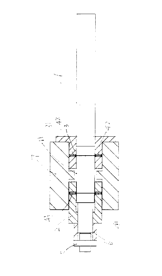
[0033] The present invention will be further described below in conjunction with the accompanying drawings.

[0034] see figure 1 As shown, an adjustable detection rod assembly includes a detection rod 1 with a conical side surface 11, a first positioning sleeve 2, a second positioning sleeve 3, a first positioning rod 41, a second positioning rod 42, and a nut 5 , the taper of the conical side surface 11 is 1:50, the detection rod 1 is provided with an external thread on the surface near the conical top end, the nut 5 can be screwed on the external thread at one end of the detection rod 1, and the nut 5 can directly touch the The first positioning sleeve 2 or the second positioning sleeve 3 is pressed tightly or indirectly through the spacer 6 . Both the first positioning sleeve 2 and the second positioning sleeve 3 can be sleeved on the inspection rod 1 and can slide along the axial direction of the inspection rod 1 at the same time, and one end surface of the second...


PUM


Abstract

The invention discloses an adjustable check bar component and a using method. According to an isotropic equal-dividing principle, manufacture errors on a circumference are equally divided to positions all around. According to structural characteristics of a bearing saddle and a nut seat, a designed tool can eliminate the phenomenon that multiple holes are not coaxial due to the manufacture errors of the holes regardless of hole positioning or hole plane positioning, the axis of a check bar is consistent with that of a bearing saddle bore or a nut seat bore, and requirements on installation precision are met. A first positioning rod and a second positioning rod of the adjustable check bar component can be replaced by a first positioning rod in the other size and a second positioning rod in the other size, and bearing saddle bores or nut seat bores with different apertures can be coaxially detected. The set of the first positioning rods and the set of the second positioning rods of the adjustable check bar component can replace concentric check sleeves of various specifications. The adjustable check bar component is applicable to coaxially detecting the bearing saddle bores or nut seat bores in various sizes, and production cost is reduced. Besides, the adjustable check bar component is convenient to assemble and disassemble when used, and the phenomenon of violent operation such as forced installation and knocking is avoided.

Description

[0001] technical field [0002] The invention belongs to the field of mechanical manufacturing, relates to an adjustable detection rod assembly, and also relates to a coaxial detection method for a bearing seat hole or a screw nut seat hole by using the adjustable detection rod assembly. Background technique [0003] The typical support structure of the ball screw pair is generally composed of two ends of the supporting bearing seat and the middle screw nut seat. bore coaxial). If the coaxiality error between the bearing seat hole and the screw nut seat hole is large, it will cause the increase of the disturbance of the screw and the increase of the radial bias load, which will cause the temperature rise and thermal deformation of each link of the screw shaft system. A series of serious consequences such as large torque and increased torque. In the prior art, concentric inspection rods and concentric inspection sleeves are generally used for three-hole coaxial inspection, ...

Claims


Application Information

Patent Timeline
Patent Type & Authority Applications(China)
IPC IPC(8): G01B5/252
Inventor 白连杰
Owner SUZHOU JIANG YUAN PRECISION MACHINERY
Why Eureka
Try Eureka