Micromechanical gyroscope drive method

A technology of a micromachined gyroscope and a driving method, which is applied in the direction of gyroscopic effect for speed measurement, gyroscope/steering sensing equipment, measuring device, etc. System instability and other problems to achieve the effect of improving stability

Active Publication Date: 2012-10-03
ZHEJIANG UNIV
View PDF3 Cites 8 Cited by
  • Summary
  • Abstract
  • Description
  • Claims
  • Application Information

AI Technical Summary

Problems solved by technology

[0004] The existing micro-mechanical gyro driving method only guarantees the stability of the amplitude of the driving mode detection signal, and its frequency changes in real time, which affects the stability of the micro-mechanical gyro system.
Taking the phase and amplitude double-closed-loop driving method as an example, when the driving frequency changes, the phase shifts generated by frequency-related modules such as filters in the system are different at different driving frequencies, which makes the phase-locked The driving mode resonance frequency tracked by the technology is not the real resonance frequency, but there is a deviation from the real frequency, and the deviation changes with the driving frequency. At this time, the phase difference between the driving displacement signal and the driving force signal is also Changes with the change of driving frequency, which leads to the instability of gyro signal detection
Therefore, the existing MEMS drive method itself will bring certain instability to the MEMS system

Method used


Image

  • Micromechanical gyroscope drive method
  • Micromechanical gyroscope drive method
  • Micromechanical gyroscope drive method

Examples


Embodiment Construction

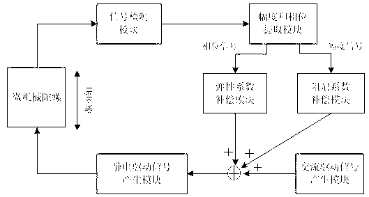
[0019] Such as figure 1 As shown, the steps of the micromachined gyroscope driving method are as follows:

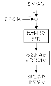
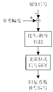
[0020] 1) Generate two mutually orthogonal signals through the AC drive signal generation module, and use one of them as the AC drive signal, generate the elastic coefficient compensation signal through the elastic coefficient compensation module, and generate the damping coefficient compensation signal through the damping coefficient compensation module. The AC drive signal, the elastic coefficient compensation signal and the damping coefficient compensation signal are added together and then input as an AC signal to the electrostatic drive signal generation module. The generation of two mutually orthogonal signals can be implemented through a coordinate rotation digital computer algorithm or It is realized by methods such as direct digital frequency synthesis;

[0021] 2) The electrostatic driving signal generation module generates an electrostatic driving signal acco...


PUM


Abstract

The invention discloses a micromechanical gyroscope drive method, which comprises four steps of generating an AC (alternating current) signal, generating a static drive signal, detecting the signals and extracting amplitude and phase. Through the active accommodation to the disturbance inside a micromechanical gyroscope, the micromechanical gyroscope drive method can ensure that the frequency and the amplitude of a drive mode detection signal are kept constant and a phase difference between the drive mode detection signal and the AC drive signal is also kept constant. According to the invention, due to no need of tracking a resonant frequency of a drive mode, the influence to a micromechanical gyroscope system by modules such as a filter relevant to the frequency in the micromechanical gyroscope system is avoided, and the stability of the micromechanical gyroscope system can be enhanced.

Description

technical field [0001] The invention relates to a micro-mechanical gyroscope, in particular to a driving method for a micro-mechanical gyroscope. Background technique [0002] Due to the advantages of small size, low power consumption, and batch production, micromechanical gyroscopes are gradually being valued in civilian and even military fields. Stability, as a key performance index of the micromachined gyroscope system, is restricted by many factors, among which the stability of the driving displacement or driving speed signal is one of the most important factors. Therefore, a good driving method is crucial to improve the stability of the MEMS gyro system. [0003] In the prior art, the AC drive signal is generally changed to adapt to the change of the micromachined gyroscope parameters, so as to ensure that the amplitude of the drive mode detection signal remains constant. The most representative method in the prior art is the phase and amplitude double closed-loop met...

Claims


Application Information

Patent Timeline
IPC IPC(8): G01C19/5776
Inventor 朱辉杰金仲和胡世昌刘义东
Owner ZHEJIANG UNIV
Why Eureka
Try Eureka