Novel accurate measuring method of anisotropic parameter of rock

An anisotropic and precise measurement technology, which is applied in the analysis of solids using sound waves/ultrasonic waves/infrasonic waves, can solve problems such as inability to accurately obtain five stiffness constants of rock samples, inaccurate C13, and no consideration of transmission delays, etc.

Inactive Publication Date: 2012-10-03
XIAN UNIV OF POSTS & TELECOMM
View PDF7 Cites 17 Cited by
  • Summary
  • Abstract
  • Description
  • Claims
  • Application Information

AI Technical Summary

Problems solved by technology

[0007] 1. The traditional measurement method of the propagation velocity of the acoustic signal in the rock sample does not take into account the transmission delay and filtering effect of the acoustic-electric conversion characteristic of the sound source and the acoustic-electric conversion characteristic of the receiver on the measured acoustic signal, thus obtaining There will be a certain difference between the propagation velocity of the acoustic signal in the rock sample and the real acoustic velocity
[0008] 2. When measuring the propagation velocity of quasi-P-wave, quasi-SV-wave and SH-wave in the rock sample by the previous technology, firstly, the electric-acoustic conversion of the sound source and the acoustic-electrical conversion of the receiver are not considered. The transmission delay caused by the acoustic signal makes the measurement of the propagation speed of the quasi-P-wave, quasi-SV-wave and SH-wave in the rock sample different from the actual propagation speed
Therefore, five stiffness constants of the rock sample cannot be obtained accurately; the second is that the above measurement method can accurately obtain the four stiffness constants C of the rock sample in theory. 33 , C 11 , C 44 and C 66 , but in the 45° direction of the rock sample, the measured energy velocity V ep (45°)
This measurement method does not use the phase velocity v p (45°), but use the measured energy velocity V ep (45°) to calculate the stiffness constant C 13 , thus obtaining C 13 is not accurate

Method used


Image

  • Novel accurate measuring method of anisotropic parameter of rock
  • Novel accurate measuring method of anisotropic parameter of rock
  • Novel accurate measuring method of anisotropic parameter of rock

Examples


Embodiment Construction

[0037] The preparation method of the present invention will be further described in detail below in conjunction with the accompanying drawings and specific embodiments.

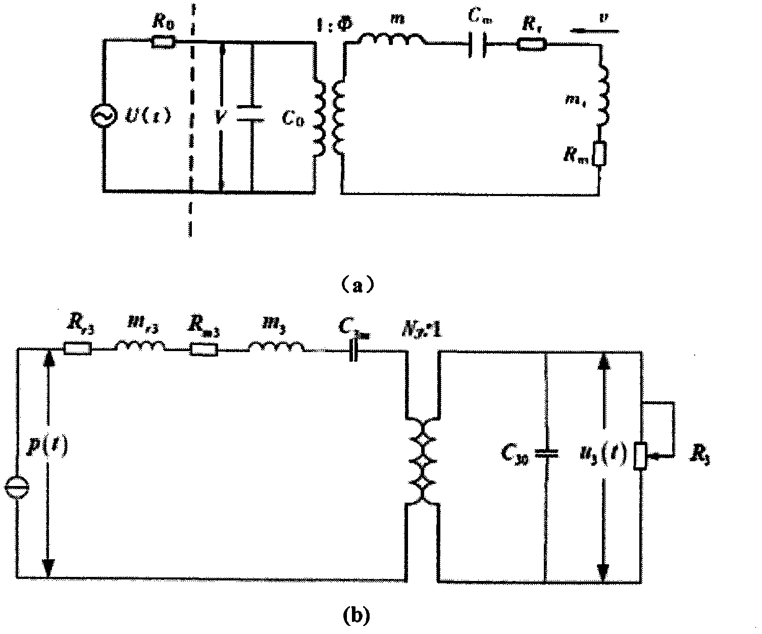
[0038] (1) Establish the electromechanical-acoustic network of the sheet-shaped compression wave transducer, and deduce its electro-acoustic impulse response and transfer function as well as its acoustic-electric impulse response and transfer function.

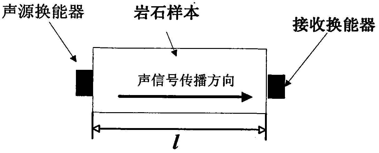
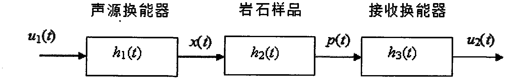
[0039] can figure 1 The acoustic measurement process shown is analogous to a signal transmission system composed of an electric-acoustic transmission subsystem (sound source), a medium (rock sample) acoustic transmission subsystem and an acoustic-electrical transmission subsystem (receiver), such as figure 2 shown. figure 2 Among them, the electrical end of the sound source is the input end of the system, and the electrical end of the receiver is the output end of the system, h 1 (t), h 2 (t) and h 3 (t) are the electrical-acoustic impulse response of t...


PUM


Abstract

The invention discloses a measuring method of the anisotropic parameters of a rock, comprising the following steps of: establishing a machine-electricity-sound network of a lamellar compression wave transducer, deducing the electricity-sound impulse response and the transmission function of the machine-electricity-sound network and the sound-electricity impulse response and the transmission function of the machine-electricity-sound network; establishing a transmission network model of the acoustic parameter measurement of a rock sample formed by a sound source system and a receiver system , and respectively calculating the delays of a compression wave and a shear wave, which are caused by the electricity-sound conversion characteristic of the sound source system and the sound-electricity conversion characteristic of the receiver system in a transmission process in the rock sample; and establishing an algorithm for determining an energy angle of a P-wave, which corresponds to the direction of a phase angle of 45 degrees, for the anisotropic rock sample to ensure that the phase velocity of the P-wave in the direction of the phase angle of 45 degrees is accurately acquired by calculating energy velocity measured in the direction of the energy angle, thereby calculating the stiffness constant C13 of the rock sample. The measuring method is accurate in calculation result and suitable for the technical field of rock physics.

Description

technical field [0001] The invention belongs to the technical field of rock physics and relates to a new method for accurately measuring rock anisotropy parameters. Background technique [0002] The measurement device for the propagation velocity of the acoustic signal in the rock sample (abbreviated as the rock sample) is as follows: figure 1 shown. It consists of a sheet sound source transducer (referred to as sound source), a sheet receiving transducer (referred to as receiver) and rock samples. figure 1 where l is the length of the rock sample. The electric driving signal excites the sound source to emit an acoustic signal, which propagates through the rock sample to the acoustic wave receiver, converts it into an electrical signal, and records it. The traditional method of measuring the propagation velocity of the acoustic signal in the rock sample is: the moment when the electric drive signal excites the sound source is taken as the start time of the radiated acoust...

Claims


Application Information

Patent Timeline
Patent Type & Authority Applications(China)
IPC IPC(8): G01N29/07
Inventor 法林巩稼民李国辉郑雅娟张延东申宁范瑾张雯
Owner XIAN UNIV OF POSTS & TELECOMM
Why Eureka
Try Eureka