
Laser ranging method

A technology of laser ranging and emitting laser, which is applied in the field of laser ranging to solve the problem of ranging blind spots, improve functions, and improve functions

Inactive Publication Date: 2012-10-03
ZHONGSHAN BAILENG PHOTOELECTRIC
View PDF0 Cites 25 Cited by
  • Summary
  • Abstract
  • Description
  • Claims
  • Application Information

AI Technical Summary

Problems solved by technology

[0004] The purpose of the present invention is to provide a method of laser ranging, which solves the problem of the echo peak and the blind area where the echo pulse and the parasitic pulse overlap

Method used


Image

  • Laser ranging method
  • Laser ranging method
  • Laser ranging method

Examples


Embodiment Construction

[0019] The present invention will be described in detail below in conjunction with the accompanying drawings. As a part of this specification, the principle of the present invention will be described through embodiments. Other aspects, features and advantages of the present invention will become clear at a glance through the detailed description.

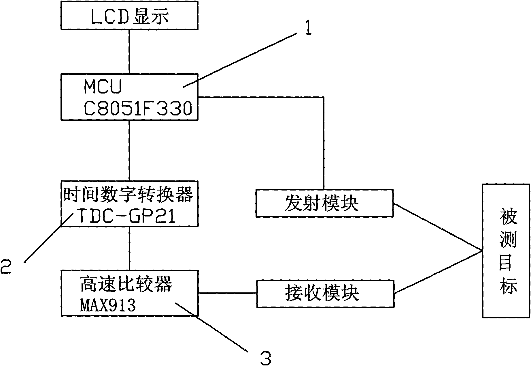
[0020] Such as figure 1 As shown, a method of laser ranging, including a time-to-digital converter 2 for timing, an MCU1 for controlling the threshold of a high-speed comparator 3, a transmitting module for emitting laser pulses, and a receiving module for receiving laser pulses module, including the following steps:

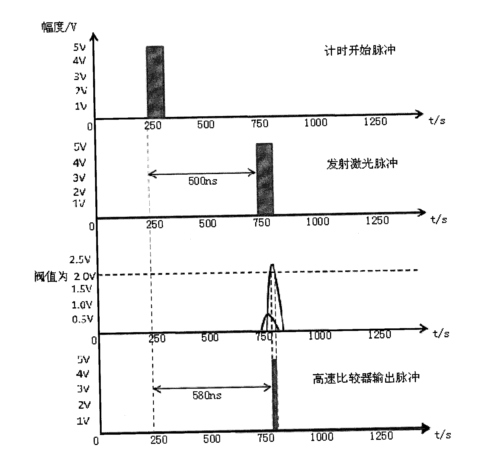
[0021] (1) MCU1 sets the initial threshold value, and emits the first pulse to trigger the time-to-digital converter 2 to start counting.

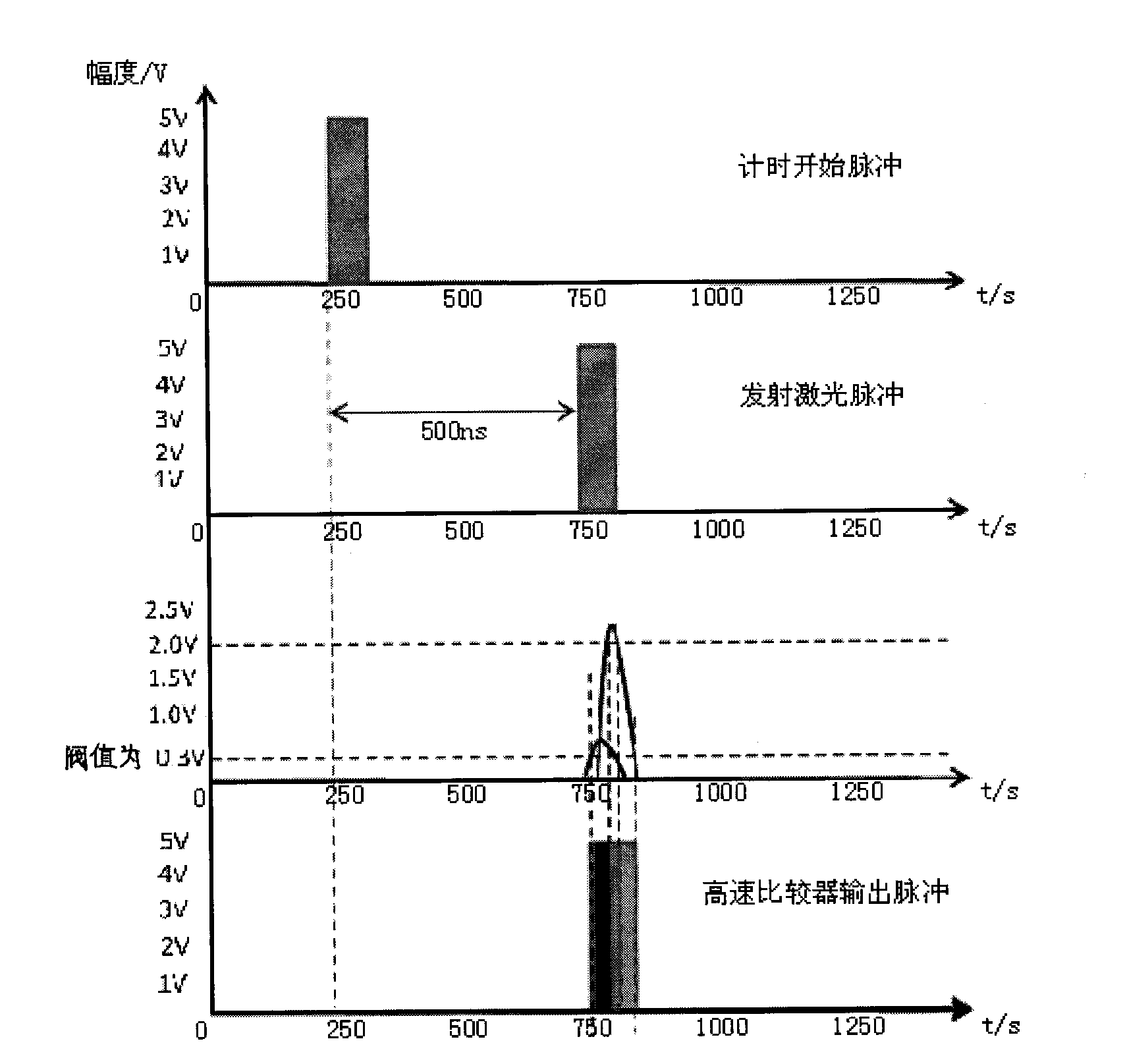
[0022] (2) Send a second pulse at an interval of 500ns to trigger the transmitting module to emit laser light, and at the same time turn on the receiving module to receive the ec...


PUM


Abstract

The invention discloses a laser ranging method. The laser ranging method includes that an initial threshold value is set by an MCU (microprogrammed control unit), and a first pulse is emitted to trigger a time-to-digital converter to start timing; a second pulse is emitted after a certain time delay to trigger an emitting module to emit laser, and simultaneously, a receiving module is opened to receive an echo signal of the laser; when the echo signal received by the receiving module is larger than the initial threshold value, a high-speed comparator outputs a measurement timing stop pulse to the time-to-digital converter, the MCU reads time difference of the measured earlier pulse and the measured later pulse of the time-to-digital converter so as to compute the measurement distance and drive an LCD (liquid crystal display) to display a measurement result in real time, if the echo signal received by the receiving module is not larger than the initial threshold value, the MCU sets the threshold value to a lower threshold value, the time-to-digital converter and the receiving module are initiated to enter a ranging procedure with the low threshold, when an echo signal is larger than the low threshold value, the high-speed comparator outputs a measurement timing stop pulse to the time-to-digital converter, and if the echo signal is not larger than the low threshold value, the ranging procedure is terminated.

Description

technical field [0001] The invention relates to a photoelectric combination method for measuring the distance to a measured object, in particular to a laser distance measuring method for short-distance ranging without blind spots. Background technique [0002] At present, the ranging capability and the ranging blind area are a pair of contradictions to be solved by the pulse laser range finder. For the pulse laser range finder, the ranging blind zone is a key parameter, which refers to the shortest measurable distance of the pulse laser range finder. Existing pulsed laser range finders with a range of 1Km all have a ranging blind zone (generally 5m to 15m). There are three main reasons for the ranging blind area: first, the blind area of ​​the pulse laser time-of-flight measurement method itself; second, the blind area caused by the saturation or even damage of the photoelectric receiving diode due to the excessive peak power of the target echo; third, It is the parasitic ...

Claims


Application Information

Patent Timeline
IPC IPC(8): G01S17/08
Inventor 谭朝晖张伟灿
Owner ZHONGSHAN BAILENG PHOTOELECTRIC
Learn More