Control method of shutter type 3D eyeglass

A technology of 3D glasses and a control method, which is applied to optics, instruments, electrical components, etc., can solve the problems of complex structure, strong sense of pressure, and unfavorable health, and achieve the effect of direct adjustment and good effect.

Inactive Publication Date: 2012-10-03
沈冬杰
View PDF0 Cites 2 Cited by
  • Summary
  • Abstract
  • Description
  • Claims
  • Application Information

AI Technical Summary

Problems solved by technology

[0003] However, this traditional shutter-type 3D glasses also has the following disadvantages: this traditional shutter-type 3D glasses can only quickly switch the video perceived by the left and right eyes, that is, realize the function of opening and closing, thereby producing a three-dimensional effect, but not It does not take into account the visual impact caused by the distance between the user and the 3D TV, that is, if the user is relatively close to the 3D TV, he will often feel glare due to the strong light. The longer the viewing time, the easier the vision Fatigue is bad for health. Therefore, if you can manually adjust the brightness of the shutter 3D glasses (that is, the light transmittance of the liquid crystal lens), it will greatly facilitate the user's needs in use.
[0007] In addition, the current shutter-type 3D glasses, because its start-up control module is generally divided into two parts (such as a battery and a circuit board), which are respectively arranged in two temples. The shutter-type 3D glasses with this structure have both temples. It is designed as a two-layer sandwich structure, and its internal space is used for wiring. Therefore, this kind of glasses are generally large in size and heavy in weight. When worn for a long time, the pressure is strong, the structure is also relatively complicated, and the power loss in the transmission process Also larger and more expensive

Method used


Image

  • Control method of shutter type 3D eyeglass
  • Control method of shutter type 3D eyeglass
  • Control method of shutter type 3D eyeglass

Examples


Embodiment 1

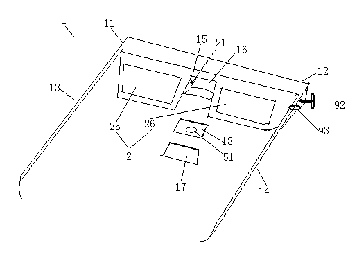
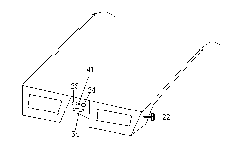
[0033] Such as Figure 1-3 As shown, Embodiment 1 of the present invention provides a shutter type 3D glasses. The shutter type 3D glasses comprise a spectacle frame 1, a liquid crystal spectacle lens 2 and a start control device 3, and the spectacle frame 1 comprises a left spectacle frame 11, a right spectacle frame 12, a left spectacle leg 13, a right spectacle leg 14, and connecting The middle nose pad 15 of the left spectacle frame 11 and the right spectacle frame 12, the middle nose pad 15 is a hollow structure, including an accommodating chamber 16 formed by the depression of the inner side surface of the middle nose pad 15, and the accommodating chamber 16 is covered. The cover 17 .

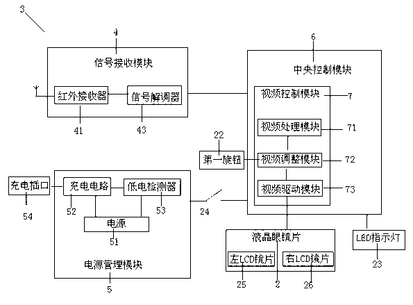
[0034] The start control device 3 includes a signal receiving module 4, a power management module 5 and a central control module 6, and the liquid crystal spectacle lens 2 is electrically connected to the start control device 3; the signal receiving module 4, the power management module ...

Embodiment 2

[0048] Embodiment 2 of the present invention provides a method for controlling shutter-type 3D glasses.

[0049] After using the shutter-type 3D glasses in Embodiment 1, the following control method can be used to operate the shutter-type 3D glasses.

[0050] Step S101, using the signal receiving module 4 to receive a synchronous video signal and decoding it into a first video synchronous signal, specifically including: using the infrared receiver 41 to receive a synchronous video signal, and using the signal decoder 43 to convert the synchronous video signal decoding the signal into a first video synchronization signal;

[0051] Step S102, using the power management module 5 to provide the power supply 51 and monitor the state of the power supply 51, reminding the user to charge the power supply when the voltage of the power supply 51 is lower than the first threshold, specifically including: when the low battery detector 53 monitors When the voltage to the power supply 51 i...

Embodiment 3

[0056] Such as Figure 7 As shown, Embodiment 3 of the present invention provides another shutter-type 3D glasses. The difference from Embodiment 1 is that the structure of the video control modules is different, and they can be used interchangeably. The video control module 7 in the third embodiment includes a video processing module 74, a parameter identification and storage module 75, a digital phase-locked loop frequency generation and phase control module 76, an LCD timing generation module 77, an LCD timing adjustment module 78 and an LCD driver module 79.

[0057]That is, the technical solution of the third embodiment is middle, the video control module includes a video processing module, a parameter identification and storage module, a digital phase-locked loop frequency generation and phase control module, an LCD timing generation module, an LCD timing adjustment module and an LCD A drive module; wherein, the video processing module is used to process the first video...


PUM


Abstract

The invention discloses a control method of a shutter type 3D eyeglass. The shutter type 3D eyeglass comprises an eyeglass frame, a liquid crystal eyeglass lens and a start control device, wherein the start control device comprises a signal receiving module, a power supply management module and a central control module, the central control module comprises a video control module, and the video control module comprises a video processing module, a video regulating module and a video driving module; the liquid crystal eyeglass lens comprises a wire connecting terminal, the wire connecting terminal is connected to the video driving module, and the wire connecting terminal penetrates through a left eyeglass frame and a right eyeglass frame which are close to middle nasal supports of the eyeglass frame to extend into a containing cavity; the left eyeglass frame or the right eyeglass frame comprises a first rotary knob, the first rotary knob is connected to the video regulating module, the first rotary knob is used for manually regulating the size of the amplitude value of a second video synchronizing signal received by the video regulating module by a user, and the light transmission rate of the liquid crystal eyeglass lens can be directly manually regulated in the way.

Description

technical field [0001] The invention relates to a control method of shutter type 3D glasses, in particular to a control method of shutter type 3D glasses with simple structure and capable of manually adjusting light transmittance. Background technique [0002] Common shutter-type 3D glasses generally include a frame and temples, wherein the frame includes two liquid crystal lenses and a signal receiver, which is used to receive wireless signals (such as infrared video signals, wireless audio signals) emitted by 3D TVs, And decode the wireless signal, from which the video and audio synchronization signals are decoded. The circuit board and battery are packaged in the mirror leg. The circuit board includes a central processing and control unit (such as a central processing chip CPU or a microcontroller MCU, etc.), video Circuit structures such as signal drive circuit and audio signal drive circuit, which can synchronize the video synchronization signal and audio synchronizatio...

Claims


Application Information

Patent Timeline
IPC IPC(8): G02B27/22H04N13/04
Inventor 沈冬杰
Owner 沈冬杰
Why Eureka
Try Eureka