Solar tracker

A solar tracker and cavity technology, applied in the field of solar trackers, can solve the problems that mobile devices cannot realize tracking functions, high cost, and many electronic components

Inactive Publication Date: 2012-10-03
苏州市伦琴工业设计有限公司
View PDF7 Cites 8 Cited by
  • Summary
  • Abstract
  • Description
  • Claims
  • Application Information

AI Technical Summary

Problems solved by technology

One is to use a set of clock-type mechanical system that can be pre-adjusted to drive the photovoltaic panel to rotate in real time as the time of the day passes. This kind of system is usually debugged by the debugging master during installation according to the longitude and latitude of each place. After the debugging is completed, The tracking system operates in real time according to the principle of the clock system, and drives the photovoltaic panels in real time to ensure that they are facing the sun in real time. This kind of system is usually more troublesome to install. Once the location is moved, professionals need to re-adjust the tracking system, which is very inconvenient , and tracking is not available on mobile devices
The second is the sensing tracking system. Its main principle is that multiple photoelectric sensors are distributed around a tracking head, and the position of the sun is calculated according to the current difference fed back by each photoelectric sensor. The problem with this type of system is that each photoelectric sensor There will inevitably be differences in the parameters of the sensors. In this way, the accuracy of the sun position calculated according to the current value fed back is poor, and because there are many photoelectric sensors, the installation position of any one is different or damaged, which may cause accurate The accuracy is seriously insufficient, and the system has many electronic components, requires high assembly precision, and the cost is also high

Method used


Image

  • Solar tracker
  • Solar tracker
  • Solar tracker

Examples


Embodiment Construction

[0027] Below in conjunction with accompanying drawing and embodiment the present invention is further described:

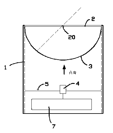
[0028] exist figure 1 In the shown embodiment, the solar tracker includes a cylindrical cavity 1; one end of the cavity 1 is provided with a shading thin plate 2; The hemispherical screen panel 3 on the shading thin plate 2; the center of the shading thin plate 2 is provided with a spot hole 20 that can introduce sunlight into the cavity 1 and irradiate it on the screen panel 3; A camera 4 is fixed to the screen board 3, and the camera 4 is electrically connected to a control circuit board 7; the control circuit board 7 includes an image analysis module and a motor control module.

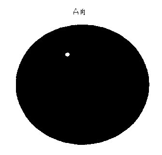
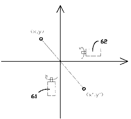
[0029] Described image analysis module at least comprises a single-chip microcomputer chip and a camera extension module, and the image processing method of this image analysis module is as follows: take the center of the orthographic projection surface of described screen board 3 as ...


PUM


Abstract

The invention provides a solar tracker and belongs to the field of solar energy collection devices. The solar tracker comprises a chamber body, a shading thin plate is disposed on one end portion of the chamber body, a hemispherical screen plate which is invertedly covered on the shading thin plate is arranged in the chamber body, an optical spot hole is mounted at the center of the shading thin plate, the sunshine can be guided into the chamber body by the optical spot hole to shine on the hemispherical screen plate, a camera which rightly faces to the screen plate is fixed in the chamber body, the camera is electrically connected with a control circuit board, and the control circuit board comprises an image analysis module and a motor control module. By means of the solar tracker, the sun can be accurately tracked so that a solar energy collection surface can rightly face to the sunshine, besides, the structure is simple, and the cost is low.

Description

[0001] technical field [0002] The invention relates to the field of solar energy collection equipment, in particular to a solar tracker that can automatically determine the direct sunlight direction and track the sun. [0003] Background technique [0004] With the rapid development of world industry, the energy problem is becoming more and more serious. Therefore, the development of energy-saving technology and new energy has become a major project for the sustainable development of mankind. Among them, technologies such as wind energy, tidal energy, and solar energy have been industrialized and achieved good energy-saving results. Especially for solar energy technology, it mainly consists of two aspects: solar water heaters and photovoltaic power generation. The former has been popularized by ordinary people, while the latter is widely seen in power plants, street lamps, and enterprises. [0005] For the field of solar energy technology, its solar energy collection eff...

Claims


Application Information

Patent Timeline
IPC IPC(8): G05D3/12
CPCF24J2/38Y02E10/47F24S50/20
Inventor 马根昌
Owner 苏州市伦琴工业设计有限公司
Why Eureka
Try Eureka