
Minitype car ignition switch device

A technology for ignition switches and micro-cars, applied in electric switches, electrical components, circuits, etc., can solve problems such as poor contact performance, aging of non-metallic parts, low one-time pass rate, etc., to solve high failure rate and improve product quality Life, the effect of improving the one-time pass rate

Active Publication Date: 2015-01-07
黄山顺昌汽车电器有限公司
View PDF4 Cites 0 Cited by
  • Summary
  • Abstract
  • Description
  • Claims
  • Application Information

AI Technical Summary

Problems solved by technology

However, because this type of switch is limited by the external space, the circuit part of the ignition switch is often rotated on the rear cover assembly by a contact bridge to realize the function; when the switch is in the ST position, four contacts are required on the rear cover assembly. Points are in contact with the contact bridge at the same time. Since three points determine a plane, it is bound to cause poor contact at one of the contact points. This kind of ignition switch currently on the market cannot solve this problem, often resulting in poor contact performance. At the same time The one-time pass rate of the product in the production process is also extremely low
At the same time, because the cockpit of the agricultural vehicle is not airtight, the ignition switch is easy to stick to dust or other sundries, and even in rainy days, rainwater may enter the interior of the ignition switch, causing corrosion of the metal parts of the ignition switch, accelerated aging of non-metal parts, and reduced service life. May cause a short circuit in the switch during normal operation, causing the switch to fail

Method used


Image

  • Minitype car ignition switch device
  • Minitype car ignition switch device
  • Minitype car ignition switch device

Examples


Embodiment Construction

[0019] The embodiments of the present invention are described in detail below. This embodiment is implemented on the premise of the technical solution of the present invention, and detailed implementation methods and specific operating procedures are provided, but the protection scope of the present invention is not limited to the following implementation example.

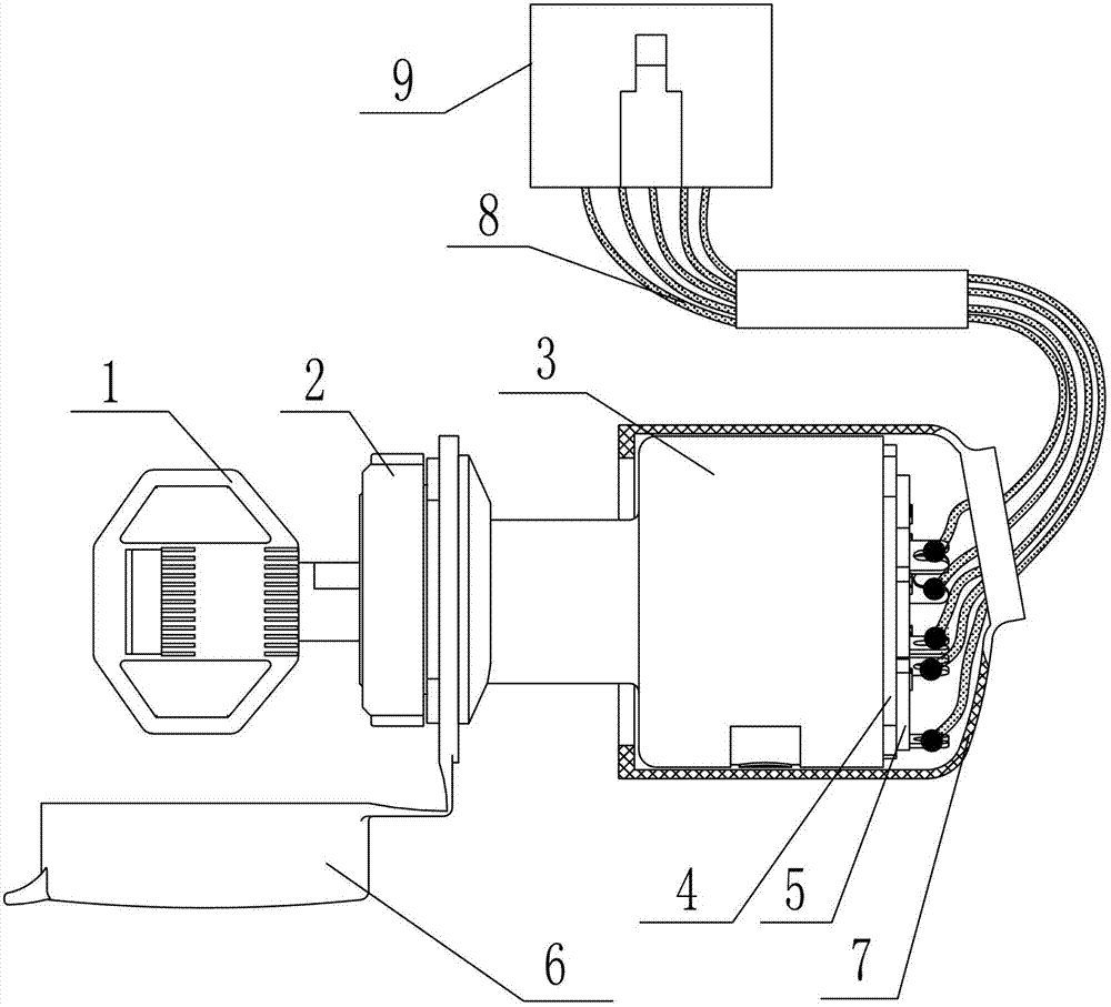
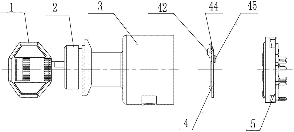
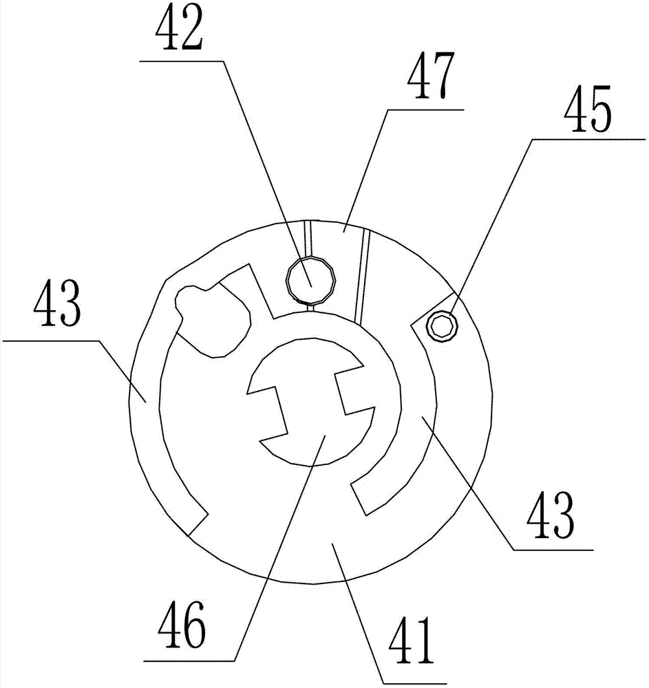
[0020] Such as figure 1 , figure 2 , image 3 and Figure 4 As shown, the present embodiment key 1, lock cylinder 2, rotating block 3, contact bridge assembly 4 and rear cover assembly 5, contact bridge assembly 4 includes contact bridge body 41, contact bridge working surface 43, elastic sheet 44 and Adjust contact 42; contact bridge working surface 43 projections are arranged on the front of contact bridge body 41, elastic sheet 44 is positioned at the back side of contact bridge body 41, and one end of elastic sheet 44 is fixed on the contact bridge body 41, and the other end and The adjustment contact 42 i...


PUM


Abstract

The invention discloses a minitype car ignition switch device which comprises a rear cover assembly and a contact bridge assembly; the contact bridge assembly comprises a contact bridge body, a contact bridge working face, an elastic sheet and a regulation contact; the contact bridge working face is arranged on the front side of the contact bridge body in a protruding way, the elastic sheet is arranged on the back surface of the contact bridge body, one end of the elastic sheet is fixed on the contact bridge body, the other end of the elastic sheet is fixedly connected with the regulation contact which is arranged on the contact bridge working face, a through hole for allowing the regulation contact to pass through is formed on the position of the contact bridge working face corresponding to the regulation contact, the rear cover assembly and the contact bridge assembly are matched for use, the middle part of the contact bridge assembly is provided with a rotary interface, and five contacts are arranged on the rear cover assembly. Due to the ignition switch, the one-time pass rate of the produced product is increased, the current situation of high aftersale failure rate is changed, and meanwhile, the waterproof and dustproof purpose is achieved and the service life of the product is prolonged.

Description

technical field [0001] The invention relates to an ignition switch device, in particular to an ignition switch device for a miniature car. Background technique [0002] At present, the working principle of the ignition switch device for miniature agricultural vehicles is: by rotating the key on the ignition lock cylinder, it can be turned to OFF (lock), ACC (electrical appliance), ON (driving), preheating (H), ST (starting) Gear position, different gear position circuit outputs are formed in the ignition assembly to realize corresponding functions. However, because this type of switch is limited by the external space, the circuit part of the ignition switch is often rotated on the rear cover assembly by a contact bridge to realize the function; when the switch is in the ST position, four contacts are required on the rear cover assembly. Points are in contact with the contact bridge at the same time. Since three points determine a plane, it is bound to cause poor contact at ...

Claims


Application Information

Patent Timeline
Patent Type & Authority Patents(China)
IPC IPC(8): H01H27/06
Inventor 孙顺水徐晖范呈祥王学祥李成林江桂宁孙宁峰
Owner 黄山顺昌汽车电器有限公司
Learn More