
Method, multimode terminal and network side device for reducing multimode mutual interference

A multi-mode terminal, multi-mode mutual interference technology, applied in electrical components, wireless communication and other directions, can solve the problem of inconsistent noise impact in continuous mode, and achieve the effect of avoiding the reduction of reception performance

Active Publication Date: 2012-10-03
ZTE CORP
View PDF3 Cites 5 Cited by
  • Summary
  • Abstract
  • Description
  • Claims
  • Application Information

AI Technical Summary

Problems solved by technology

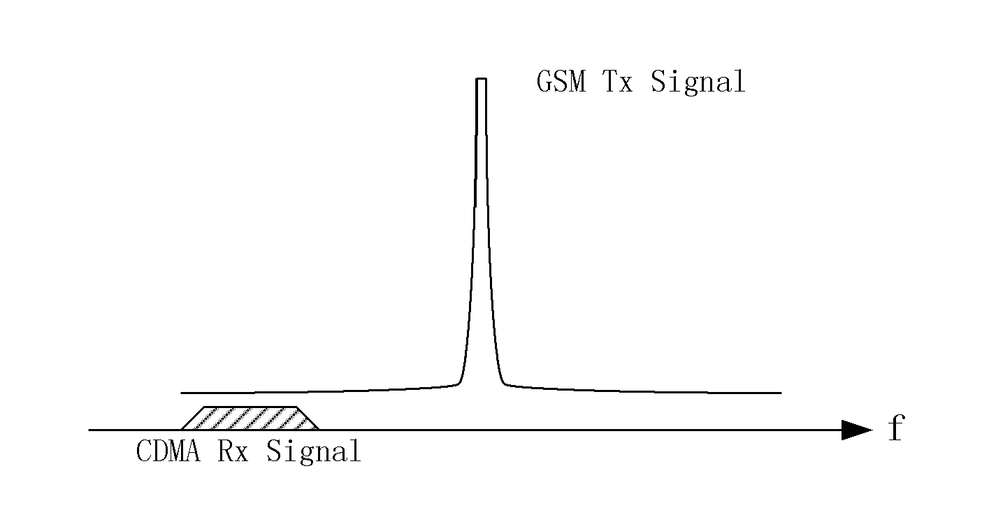
[0004] However, since GSM transmits signals in time slot mode, its uplink transmission is only carried out in 1 / 8 time slot in one frame, so the noise falling into the CDMA receiving frequency band is also in time slot mode, so its impact is inconsistent with that of continuous mode noise

Method used


Image

  • Method, multimode terminal and network side device for reducing multimode mutual interference
  • Method, multimode terminal and network side device for reducing multimode mutual interference
  • Method, multimode terminal and network side device for reducing multimode mutual interference

Examples


Embodiment 1

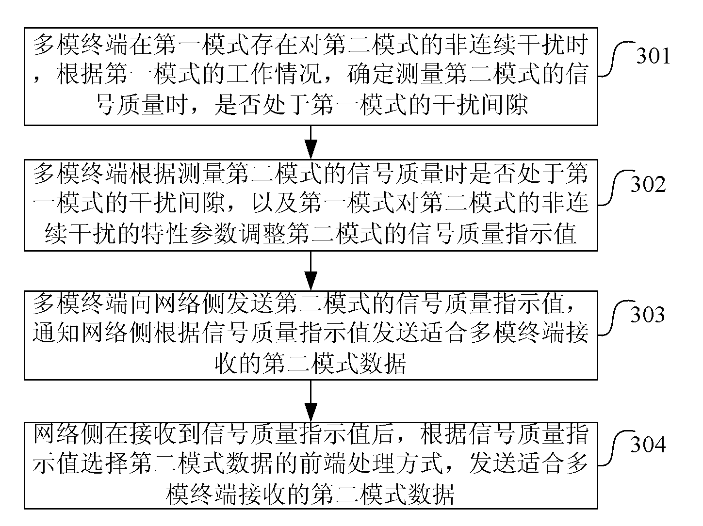
[0045] Such as image 3 As shown, the method for reducing multi-mode mutual interference in this embodiment includes:

[0046] Step 301: When the multi-mode terminal has discontinuous interference with the second mode in the first mode, according to the working conditions of the first mode, determine whether it is in the interference gap of the first mode when measuring the signal quality of the second mode;

[0047] Step 302: The multi-mode terminal adjusts the signal quality indicator value of the second mode according to whether it is in the interference gap of the first mode when measuring the signal quality of the second mode, and the characteristic parameters of the discontinuous interference of the first mode to the second mode;

[0048] The characteristic parameters of discontinuous interference include: interference signal power level P I , Interference signal sending period T and interference duration τ, etc.

[0049] When the signal quality of the second mode is m...

Embodiment 2

[0057] Such as Figure 4 As shown, the method for reducing multi-mode mutual interference in this embodiment includes:

[0058] Step 401: When the multi-mode terminal has discontinuous interference to the second mode in the first mode, the characteristic parameters of the discontinuous interference, the measured signal quality indicator value, and whether it is in the first mode when measuring the signal quality of the second mode The information of the interference gap of the mode is reported to the network side;

[0059] The characteristic parameters of discontinuous interference include: interference signal power level P I , Interference signal sending period T and interference duration τ, etc.

[0060] Step 402: The network side receives the information reported by the multi-mode terminal, and adjusts the second mode according to whether it is in the interference gap of the first mode when measuring the signal quality of the second mode, and the characteristic parameters...


PUM


Abstract

The invention discloses a method, a multimode terminal and a network side device for reducing multimode mutual interference. The method comprises that if discontinuous interference on a second mode exists when the multimode terminal is in a first mode, the multimode terminal adjusts signal quality indication values of the second mode according to characteristic parameters of the discontinuous interference and the fact that whether the multimode terminal is in an interference gap of the first mode when signal quality of the second mode is measured, and the multimode terminal sends adjusted signal quality indication values to a network side. According to the method, the multimode terminal and the network side device, the multimode terminal adjusts reported signal-to-noise ratio (SNR) values on a terminal side according to characteristics of the discontinuous interference or calculates SNR values on the network side, so that reduction of receiving performance of the terminal under the influence of the discontinuous interference is avoided.

Description

technical field [0001] The invention relates to the technical field of mobile communication terminals, in particular to a method for reducing multi-mode mutual interference, a multi-mode terminal and network side equipment. Background technique [0002] With the rapid development of mobile communication technology, mobile terminals have become the most commonly used communication tools for people; and with the continuous improvement of people's demand for mobile communication, it is difficult for a single-mode mobile terminal to meet the needs of users, and users need to integrate more Mode mobile terminal, and requires multi-mode to work simultaneously and have good performance. Now multi-mode terminals are very common, but there is a problem of mutual interference in the application of multi-mode terminals, which has a great impact on performance. Taking the working condition of a CDMA (Code Division Multiple Access) and GSM (Global System for Mobile Communications) dual-...

Claims


Application Information

Patent Timeline
Patent Type & Authority Applications(China)
IPC IPC(8): H04W88/06
Inventor 李远勇
Owner ZTE CORP
Learn More