Plug and play high performance omni coverage HDTV antenna

a high-performance, omni-coverage technology, applied in the direction of individual energised antenna arrays, resonant antennas, fixed connections, etc., can solve the problems of inherently low gain performance of broad coverage structures, radiation coverages that are often too broad or too narrow, and structures that are used today cannot achieve the desired reception, etc., to achieve easy and uniform radiation coverage and simplify the antenna structure

Inactive Publication Date: 2020-08-27
WONG GARY GWOON +2
View PDF0 Cites 0 Cited by
  • Summary
  • Abstract
  • Description
  • Claims
  • Application Information

AI Technical Summary

Benefits of technology

[0010]One of a main goal in the design of the disclosure antenna is to simplify the antenna structure such it can perform with easy and special instruction and adjustment would not be needed. It should be noted that the physical appearance and construction of the two referenced disclosure antennas are not the same as the current disclosure structure. The referenced antennas are of a single element device while the current disclosure antenna is a multi-elements device and has also a uniform radiation coverage along the horizontal plane over the upper hemisphere.
[0011]Initially, the...

Problems solved by technology

Structures in used today are unable to achieve a desire reception.
The radiation coverages are often too broad or too narrow.
However, the gain performance of the broad coverage...

Method used


Image

  • Plug and play high performance omni coverage HDTV antenna
  • Plug and play high performance omni coverage HDTV antenna

Examples


Embodiment Construction

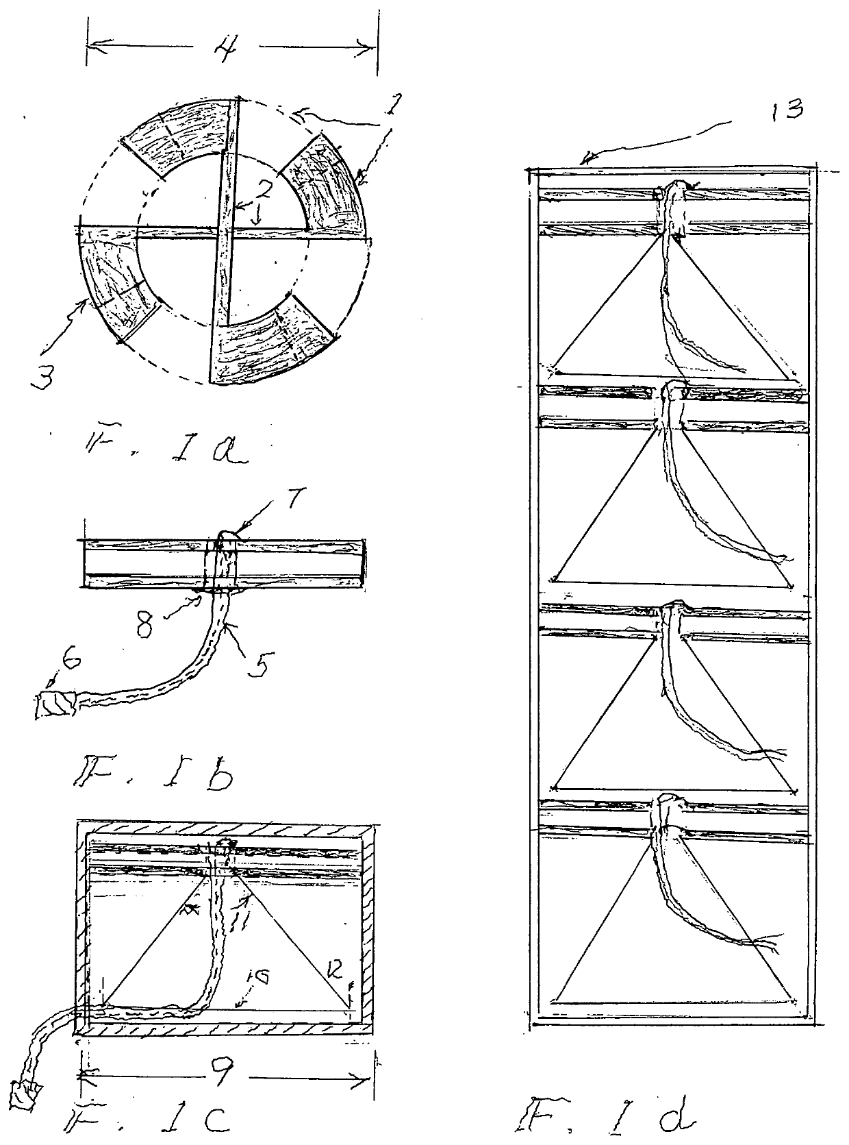
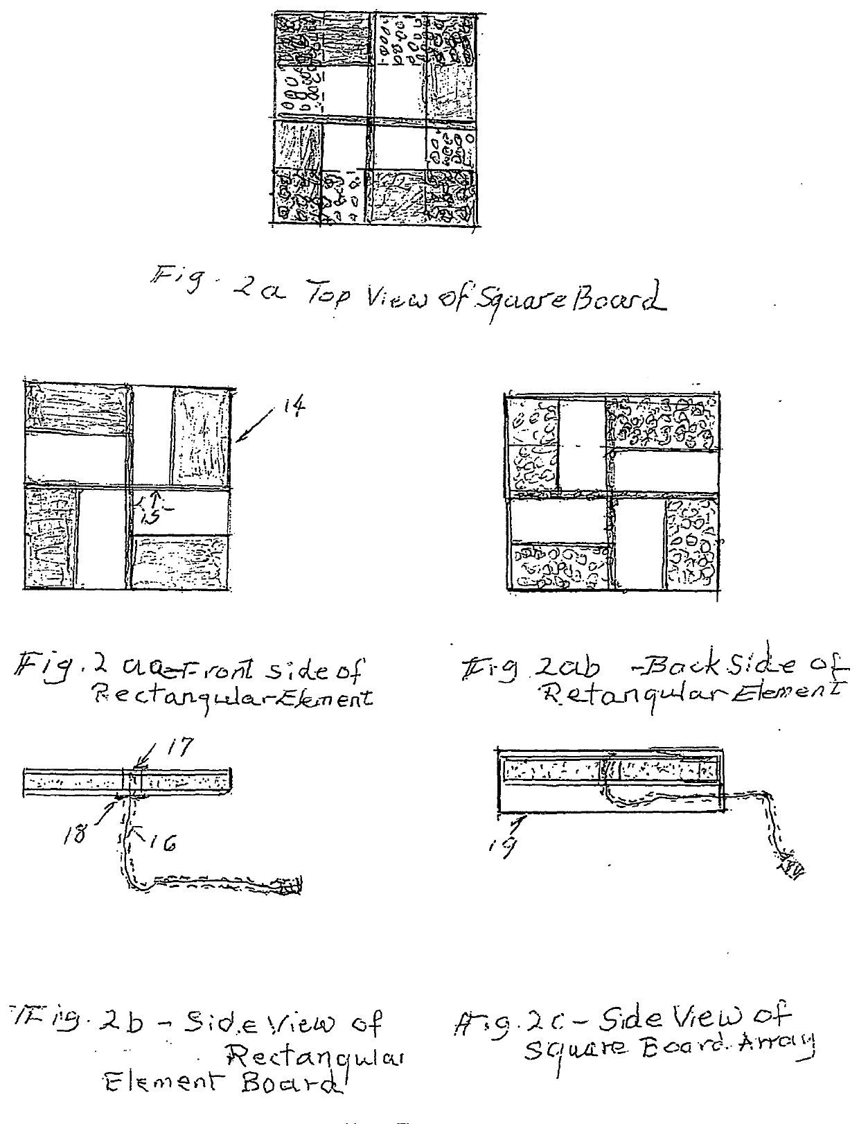
[0012]The disclosure antenna composes of eight rectangular or round radiating arms with four arms located on the top surface of a circuit board and the opposing four arms are located on the back side surface of the circuit board. The arms are spaced evenly along the four quadrants of a circle or along the four quadrants of a square circuit board. The arms are made very wide which are designed to accommodate a broad frequency bandwidth of 400 to 800 MHz and the impedance match is uniquely accomplished through the joining of the two intersecting transmission lines connecting to the top and bottom surface of circuit board radiating elements at the center of the board via a coaxial cable.

[0013]The outer copper shield of the coaxial cable is soldered to the opposing bottom of the circuit board while the center conductor of the coaxial cable is soldered to the top part of the circuit board at the center of the radiating elements.

[0014]All the interconnecting parts are working together to ...


PUM


Abstract

A highly efficient radiation structure in a compact design is described. The structure is designed to receive over the air signals in the UHF frequency band. Unlike most of the current structures, the disclosure structure consists of an array of four radiating elements and are configured to perform an uniform reception along the horizontal plane and the elements are positioned in a circle or in a square configuration and are located near the outer edge of a circular or a square shape circuit board; the elements are efficiently combined by an unique four way power combiner which is specially designed to obtain the necessary impedance match to an input coaxial cable. The entire structure consist only a few simple parts. Namely, a circuit board with the top and bottom surfaces etched on with the radiating elements and associated feed lines. A coaxial feed line terminated with a feeding connector of the F type is provided. This coaxial line provides the necessary input connection to the circuit board and also routs the receiving signal to a TV. Two circuit board designs are disclosed; one is equipped with circular dipole arms while the second circuit board is equipped with the rectangular dipole arms. On the circular dipole element design, the array structure is implemented with a cone shape ground plane which is designed to help reduce the radiation coverage below the horizons. The square aperture array is implemented without the cone shape ground plane. Both structures are protected by a plastic enclosure and both structures are configured to be simple and can be made economically.

Description

CROSS-REFERENCE TO RELATED APPLICATION[0001]This application claims the benefit of the U.S. Provisional Application No. 62 / 917,992 filed on Jan. 12, 2019. The substitute specification contains no new matters.SUMMARY OF THE INVENTION[0002]A highly compact symmetrical structure is disclosed. The subject structure is designed to maximize the reception capability of the structure to receive over the air signals.[0003]Structures in used today are unable to achieve a desire reception. The radiation coverages are often too broad or too narrow.[0004]The broad coverage structure has the advantage of receiving signals from all the surrounding-stations. However, the gain performance of the broad coverage structure is inherently low and often unable to receive signals from far away stations.[0005]The narrow coverage antenna, on the other hand, has the inherent high gain performance advantage and is able to receive the over air signal from a greater distance away. The short fall is that the rece...

Claims


Application Information

Patent Timeline
IPC IPC(8): H01Q21/06H01Q1/24H01Q1/38H01Q1/48
CPCH01R12/53H01Q9/28H01Q9/40H01Q1/38H01Q1/241H01Q1/48H01Q21/062H01Q9/065H01Q9/26H01Q21/205
Inventor WONG, GARY GWOONWONG, KALEM GWOONWONG, SAMUEL WAHON
Owner WONG GARY GWOON
Why Eureka
Try Eureka