Solenoid valve, and method for producing such solenoid valve

A solenoid valve and valve needle technology, applied in the field of manufacturing solenoid valves, can solve the problems of high production costs and achieve the effect of eliminating chip processing

Inactive Publication Date: 2012-10-03
ROBERT BOSCH GMBH
View PDF5 Cites 3 Cited by
  • Summary
  • Abstract
  • Description
  • Claims
  • Application Information

AI Technical Summary

Problems solved by technology

High production costs due to machining of the core sleeve, which is usually a turned part

Method used


Image

  • Solenoid valve, and method for producing such solenoid valve
  • Solenoid valve, and method for producing such solenoid valve
  • Solenoid valve, and method for producing such solenoid valve

Examples


Embodiment Construction

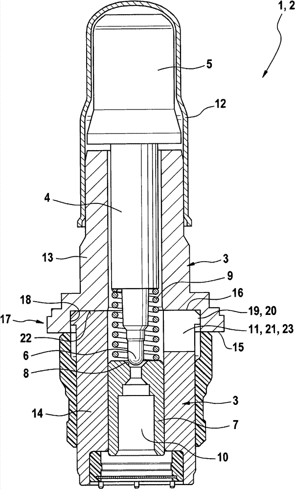
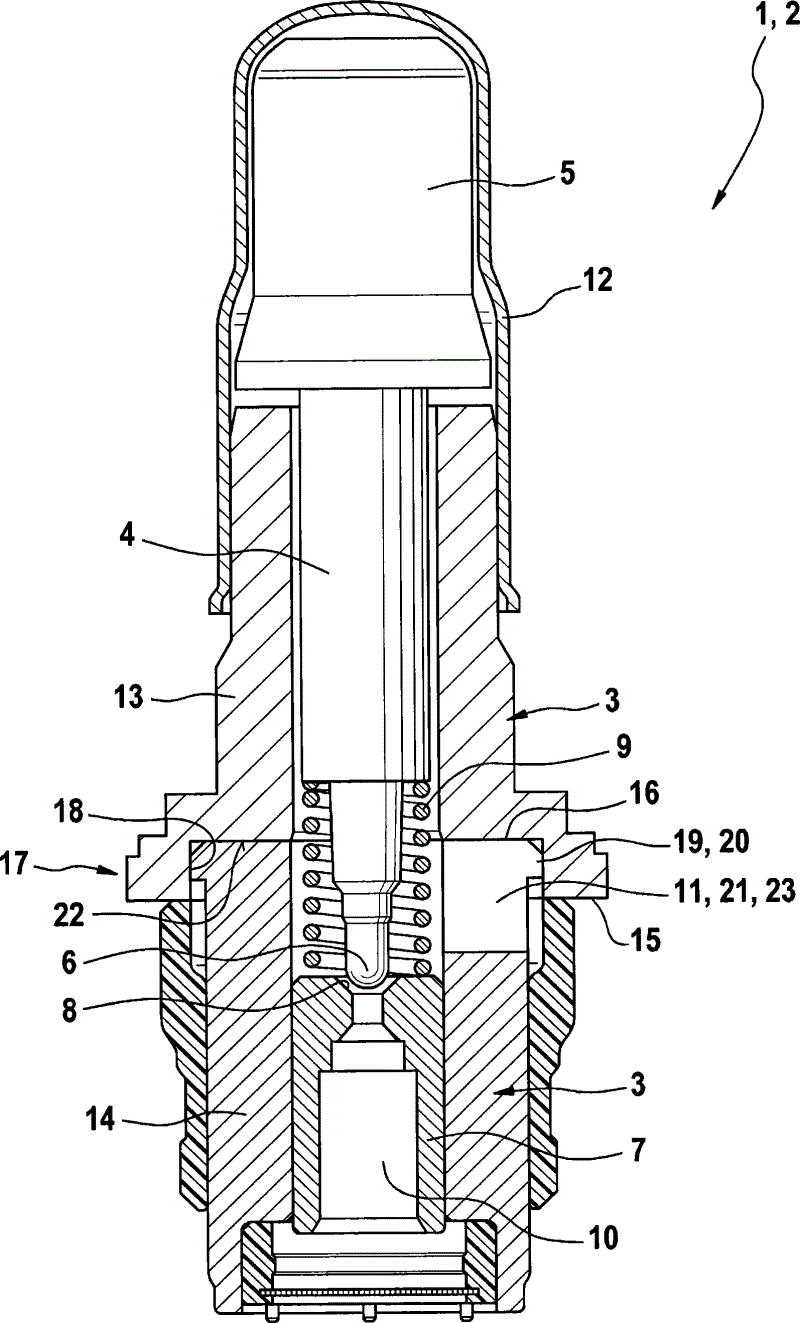
[0016] figure 1 Shown is a simplified longitudinal sectional view of the solenoid valve 1 . The solenoid valve 1 is a so-called de-energized open valve 2 which is used in a hydraulic system of a motor vehicle, in particular in a braking system such as an ESP system, an ABS system or a TSC system. The solenoid valve 1 has a core sleeve 3 in which a valve needle 4 is arranged displaceable in the longitudinal direction or axially. The valve needle 4 has an armature 5 at its end opposite its valve tip. The valve needle interacts via its valve tip 6 with a valve seat 8 formed in a valve body 7 fixed in the core sleeve 3 . One end of the coil spring 9 is close to the valve body 7, and the other end is close to the axial stop of the valve needle 4. The coil spring presses the valve needle 4 away from the valve seat 8, so that when the solenoid valve 1 is not operated Open the flow cross section in the state. When the solenoid valve 1 is opened, fluid can flow in through the axial...


PUM


Abstract

The invention relates to a solenoid valve (1) comprising a core sleeve (3), in which a valve needle (4) can be arranged in a longitudinally displaceable manner, said core sleeve (3) having at least one radial opening (11) in the casing wall thereof. According to the invention, the core sleeve (3) has a first sub-sleeve (13) and a second sub-sleeve (14) that axially adjoins the first sub-sleeve (13). The radial opening (11) in the connecting region (17) is designed as an end face axial recess (21) in at least one of the sub-sleeves (14). The invention further relates to a method for producing such a solenoid valve (1).

Description

technical field [0001] The invention relates to a solenoid valve having a core sleeve in which a valve needle is arranged displaceably in the longitudinal direction, wherein the core sleeve has at least one radial opening in its housing wall. [0002] The invention also relates to a method for producing a solenoid valve having a core sleeve in which a valve needle is arranged displaceably in the longitudinal direction and wherein the core sleeve has at least one radial opening . Background technique [0003] Solenoid valves of the type mentioned at the outset and methods for their production are known from the prior art. For example, they can be used as control valves and / or regulating valves in hydraulic systems, for example in motor vehicle brake systems. For this purpose, these solenoid valves have at least one core sleeve in which a valve needle is arranged or supported so as to be displaceable in the longitudinal direction. The inner cavity of the core sleeve usually...

Claims


Application Information

Patent Timeline
Patent Type & Authority Applications(China)
IPC IPC(8): B60T8/36F16K31/06F16K1/42
CPCB60T8/363F16K31/06F16K31/0665F16K31/0655Y10T29/49405B60T8/36F16K1/42
Inventor E·菲尔N·阿拉策
Owner ROBERT BOSCH GMBH
Why Eureka
Try Eureka