
Power transmission device

A power transmission device, the technology of left and right, applied in the direction of transmission device, multi-gear ratio transmission device, differential transmission device, etc., can solve the problem of reducing the control accuracy of the engagement force, and achieve the effect of preventing mutual interference between actions

Active Publication Date: 2012-10-03
HONDA MOTOR CO LTD
View PDF6 Cites 16 Cited by
  • Summary
  • Abstract
  • Description
  • Claims
  • Application Information

AI Technical Summary

Problems solved by technology

[0007] However, the above-mentioned conventional power transmission device has the following problems: for example, when the clutch piston of the left clutch pushes the left friction engagement member to the right, the slip ring bends to the right and the right friction engagement members of the right clutch come into contact with each other. Conversely, when the clutch piston of the right clutch is used to push the right friction engagement member to the left, the slip ring bends to the left and the left friction engagement members of the left clutch contact each other, so the actions of the left and right clutches interfere with each other and the engagement force The control accuracy is reduced

Method used


Image

  • Power transmission device
  • Power transmission device
  • Power transmission device

Examples


no. 1 approach

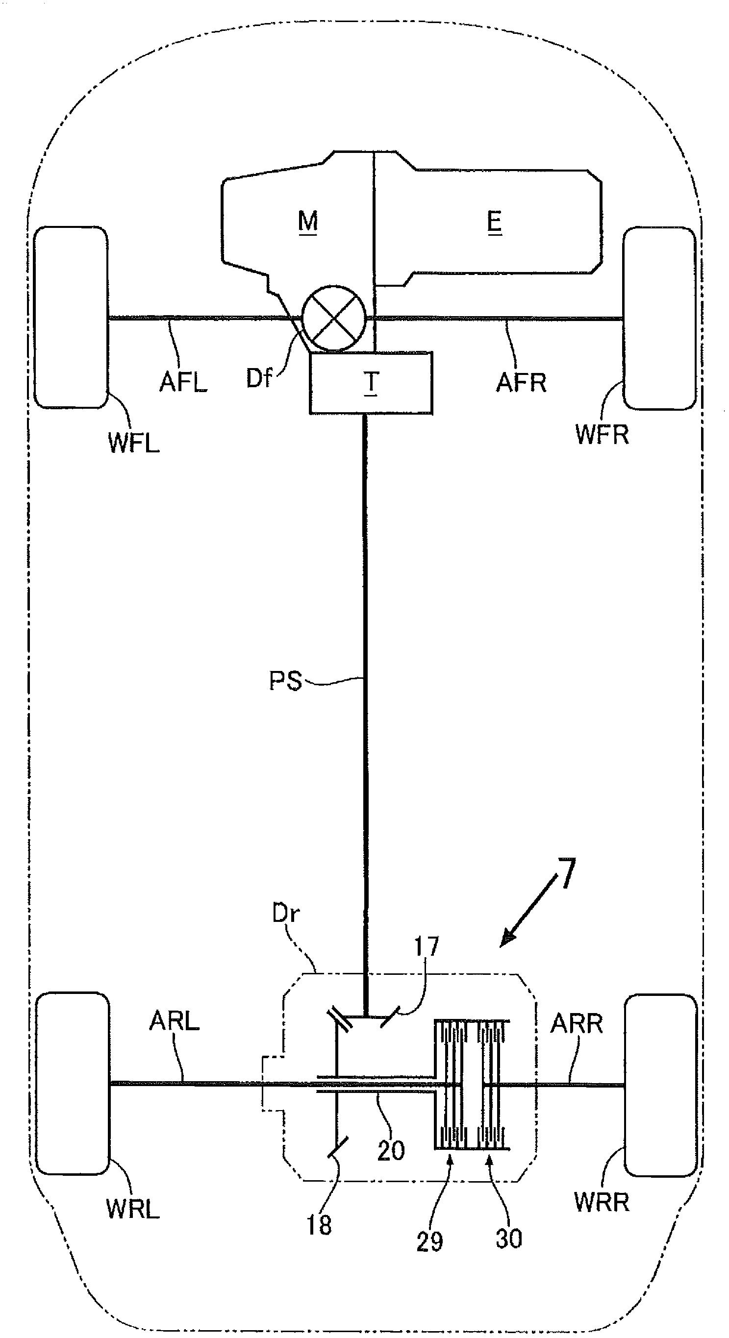
[0036] Such as figure 1As shown, a four-wheel-drive vehicle based on a front-engine / front-drive vehicle includes: front wheels WFL and WFR as main drive wheels, and the driving force of the engine E passes through the transmission M, the front differential gear Df, and the left and right axles AFL , AFR and transmitted to the main drive wheels; part of the driving force of the rear wheels WRL, WRR, front wheels WFL, WFR as auxiliary drive wheels is transmitted through the transmitter T, the propeller shaft PS, the rear differential gear Dr and the left and right axles ARL , ARR and transmitted to the secondary drive wheel.

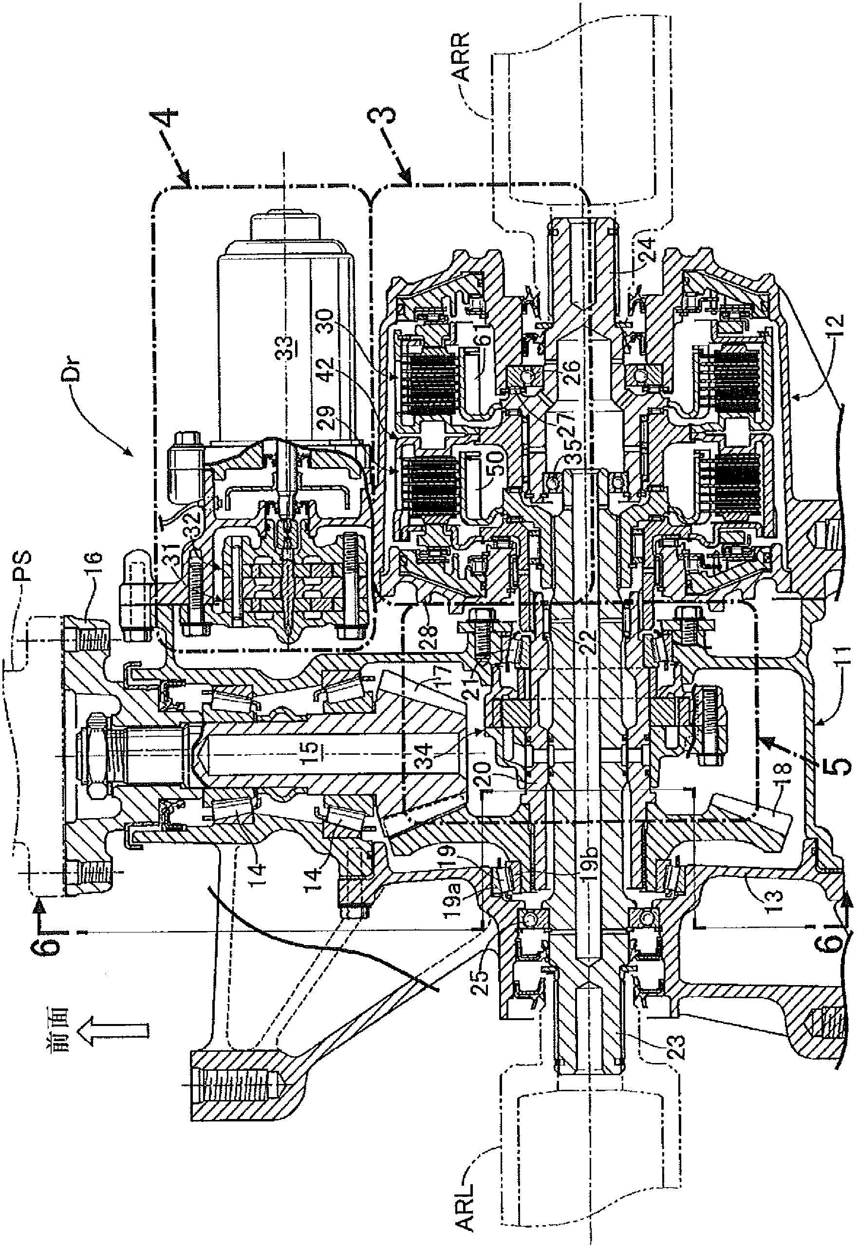
[0037] Such as figure 2 As shown, the rear differential gear Dr includes a center case 11 , a side case 12 joined to the right side of the center case 11 , and a side cover 13 joined to the left side of the center case 11 . The input shaft 15 extending in the front-rear direction of the vehicle body is rotatably supported by the center casing 11 via two...


PUM


Abstract

Since the pressing force of left and right clutch pistons (55, 63), which is subjected on the left and right disks (42b, 42d) of a shared clutch actuator (42) for left and right clutches (29, 30) that distribute the driving force of an input shaft (20) to left and right output shafts (23, 24), is ultimately transmitted from the boss (42a) of the clutch actuator (42) to a side housing (12) via thrust bearings (53, 52, 48; 41, 27) and maintained, the left and right clutches (29, 30) can engage without interference. Even if the left and right disks (42b, 42d) of the clutch actuator (42) bend from the pressing force of the clutch pistons (55, 63), the pressing force of one clutch (29, 30) is not transmitted to the other clutch (29, 30) owing to the space (a) formed therebetween, whereby the mutual interference of the movements of the left and right clutches (29, 30) is prevented.

Description

technical field [0001] The present invention relates to a power transmission device in which two clutches are arranged back-to-back in order to independently distribute the rotation of an input shaft to left and right output shafts. Background technique [0002] According to the following Patent Document 1, there is known a power transmission device in which a rear differential gear is provided with a pair of left and right clutches sharing a clutch outer, and the rear differential gear is transmitted from an engine through a propeller shaft. The input driving force is distributed to the left and right rear wheels. In the power transmission device, a slip ring is fixed to the left-right central portion of the inner peripheral spline of the clutch outer assembly. Friction engagement members are respectively arranged on the left and right of the slip ring. The clutch piston presses the left frictional engagement member against the slip ring to engage the left clutch, and the r...

Claims


Application Information

Patent Timeline
IPC IPC(8): F16H48/12F16H57/04F16D25/10F16H57/02F16H48/19F16H48/32
CPCF16D21/02F16H48/32F16H2200/2071F16H48/19F16D25/082F16D25/10F16D2021/0661F16D2021/0692F16D21/06F16D2021/0607
Inventor 秋叶良雄吉田武史今村正广铃木隆文
Owner HONDA MOTOR CO LTD
Learn More