Lighting device and method for contacting a lighting device

A lighting device and contact area technology, applied in lighting devices, lighting and heating equipment, and electrical components to assemble printed circuits, etc., can solve problems such as loss of warranty rights, and achieve the effect of firm connection, reliable contact, and firm contact

Inactive Publication Date: 2015-04-01
OSRAM GMBH
View PDF7 Cites 0 Cited by
  • Summary
  • Abstract
  • Description
  • Claims
  • Application Information

AI Technical Summary

Problems solved by technology

Here, the user's warranty rights to the manufacturer are lost and the IP classification is no longer guaranteed by the manufacturer or supplier

Method used


Image

  • Lighting device and method for contacting a lighting device
  • Lighting device and method for contacting a lighting device

Examples


Embodiment Construction

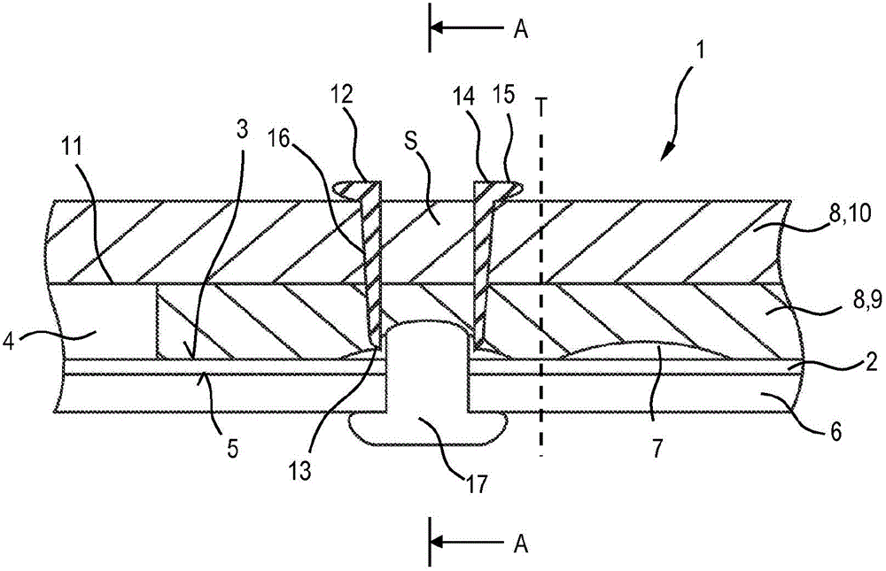
[0033] figure 1 A side sectional view of a part of the lighting device 1 according to the invention is shown.

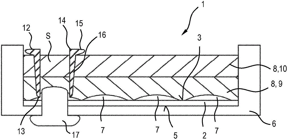
[0034] figure 2 A front sectional view of the lighting device 1 is shown.

[0035] see figure 1 with figure 2 , the lighting device 1 has a strip-shaped, flexible printed circuit board 2 , the upper or front side 3 of which is equipped with light-emitting diodes 4 arranged in series. The back side 5 of the circuit board 2 is fixed on the bottom of an elongated profile 6 with a U-shaped cross-section (see figure 2 ). The profile 6 can have silicone as its base material in order to be able to at least partially retain the flexibility of the lighting device 1 . The profile 6 can in particular be produced from an opaque material. The light-emitting diodes 4 radiate upwards and outwards from the open side of the profile 6 , wherein the profile 6 protrudes upwards beyond the equipped circuit boards 2 , 4 .

[0036] On the front side 3 of the printed circuit boar...


PUM


Abstract

A lighting device may include a printed circuit board, wherein the printed circuit board has wiring on at least one of the front side and the back side thereof, the respective wiring is covered by at least one potting layer, the lighting device furthermore has at least one electrically conductive punched bushing and the punched bushing extends through a potting layer at least to the wiring and contacts the wiring.

Description

technical field [0001] The invention relates to a lighting device having a printed circuit board, wherein the printed circuit board has wiring on its front side and / or on its rear side, and the corresponding wiring is covered by a potting layer. Furthermore, the invention relates to a method for accessing such a lighting device. Background technique [0002] DE 10 2007 04 301 A1 shows a bushing for contacting a flexible printed circuit board of a lighting module, said bushing being arranged in a filler material which is in turn surrounded outwardly by a protective layer. The bushing is placed on the circuit board during production, ie before the filling material is applied, and is exposed by cutting the lighting module in order to make contact with the lighting module. [0003] For example, LED lighting strips with strip-shaped circuit boards are known from the LINEAR Light series (linear light series) from Osram, wherein the circuit board is equipped with light-emitting di...

Claims


Application Information

Patent Timeline
Patent Type & Authority Patents(China)
IPC IPC(8): F21S4/00H05K3/32
CPCH01L2924/0002H05K2201/10401H05K2201/10106H05K3/284H05K3/325H05K1/189H05K2203/1189H01L2924/00
Inventor 安德烈亚斯·坎普弗拉特斯特芬·施特劳斯
Owner OSRAM GMBH
Why Eureka
Try Eureka