Heat exchanger for thermoelectric generators

A technology of thermoelectric generators and heat exchangers, applied in heat exchange equipment, thermoelectric devices that only use the Peltier or Seebeck effect, heat sinks, etc., can solve the problems that hinder the effective use of exhaust gas energy, differential heat transfer coefficient, etc., and achieve improvement Energy efficiency, homogenization, and reduction of harmful substances

Inactive Publication Date: 2012-10-03
ROBERT BOSCH GMBH
View PDF6 Cites 3 Cited by
  • Summary
  • Abstract
  • Description
  • Claims
  • Application Information

AI Technical Summary

Problems solved by technology

[0005] Channels without ribs have poor heat transfer coefficients and prevent efficient use of exhaust gas energy

Method used


Image

  • Heat exchanger for thermoelectric generators
  • Heat exchanger for thermoelectric generators
  • Heat exchanger for thermoelectric generators

Examples


Embodiment Construction

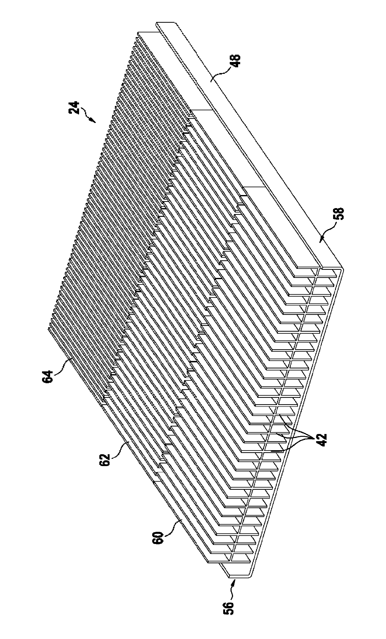
[0026] figure 1 A possible configuration of a heat exchanger with ribbed heat channels and three columns of thermoelectric generators (TEGs) along the flow direction is shown.

[0027] In a possible embodiment, the heat exchanger 10 can have two channels 12 , 14 for the cooling medium 16 as a heat sink. In this case, the one channel 12 for the cooling medium 16 runs on the bottom side 18 of the heat exchanger 10 , and the second channel 14 for the cooling medium 16 runs on the upper side 20 of the heat exchanger 10 .

[0028] An additional channel 24 serving as a heat source for a heating medium 26 is located in the middle 22 of the heat exchanger 10 .

[0029] The channels 12 , 14 for the cooling medium 16 and the channels 24 for the heating medium 26 extend in mutually parallel planes and form a stack 28 with a stack axis 30 here. Viewed along the stack axis 30 , the channels 12 , 14 for the cooling medium 16 and the channels 24 for the heating medium 26 are arranged alter...


PUM


Abstract

The invention relates to a heat exchanger (10) for thermoelectric generators, comprising at least two channels (12, 14) for a cooling medium (16) and at least one channel (24) for a heating medium (26). The inner region (54) of the at least one channel (24) for the heating medium (26) is provided with ribs (42). According to the invention, said ribs (42) are applied in increasing number in the heating flow direction, contributing, inter alia, to a more efficient use and a homogenisation of the heat flow.

Description

Background technique [0001] Depending on the model, up to 35% of the waste heat generated by vehicles is often discharged into the environment without being used. Efficient use of this thermal energy, however, results in a reduction in fuel demand. [0002] The solution to harnessing this exhaust heat is the Thermoelectric Generator (TEG). When there is a temperature difference along the conductors, a voltage is generated at the free ends of the two interconnected conductors. Devices for generating energy from the heat of exhaust gases are known and disclosed, for example, in DE 10 2008 005 334 A1. [0003] In order to utilize the energy of the exhaust gases better, the flow channels through which the heat-dissipating fluid flows partially have reinforcements in the form of ribs, which are usually arranged at equal distances from one another. The ribs increase the surface area of ​​the flow channel and ensure better heat transfer between the heat-dissipating fluid and the f...

Claims


Application Information

Patent Timeline
Patent Type & Authority Applications(China)
IPC IPC(8): H01L35/30
CPCH01L35/30F28F3/025F28F2215/04F28F3/02H10N10/13
Inventor P.格拉泽
Owner ROBERT BOSCH GMBH
Why Eureka
Try Eureka