
Optical transceiver module, passive optical network system, optical fiber detection method and system

An optical transceiver module and optical fiber adapter technology, applied in the field of optical communication, can solve the problems of fault determination and delimitation of difficult-to-branch optical fibers, large power loss of optical splitters, and rising costs, and achieve simple and effective fault detection and diagnostic analysis. , The effect of reducing the difficulty of construction and reducing the cost of testing

Active Publication Date: 2012-10-03
HUAWEI TECH CO LTD
View PDF5 Cites 22 Cited by
  • Summary
  • Abstract
  • Description
  • Claims
  • Application Information

AI Technical Summary

Problems solved by technology

[0006] However, in the passive optical network system, the optical distribution network usually uses a passive optical splitter for signal branching / coupling. Due to the large power loss of the optical splitter, it is difficult for the optical transceiver module using the above-mentioned shared optical emission components Direct fault identification and demarcation of branch fibers
Therefore, when using the above-mentioned solution for optical fiber detection, it is still necessary to combine other means, such as adding optical reflectors to branch optical fibers for fault location, etc., which will not only increase the cost, but also increase the difficulty of construction

Method used


Image

  • Optical transceiver module, passive optical network system, optical fiber detection method and system
  • Optical transceiver module, passive optical network system, optical fiber detection method and system
  • Optical transceiver module, passive optical network system, optical fiber detection method and system

Examples


Embodiment Construction

[0022] The optical transceiver module and optical fiber detection method provided by the present application will be described in detail below in conjunction with specific embodiments.

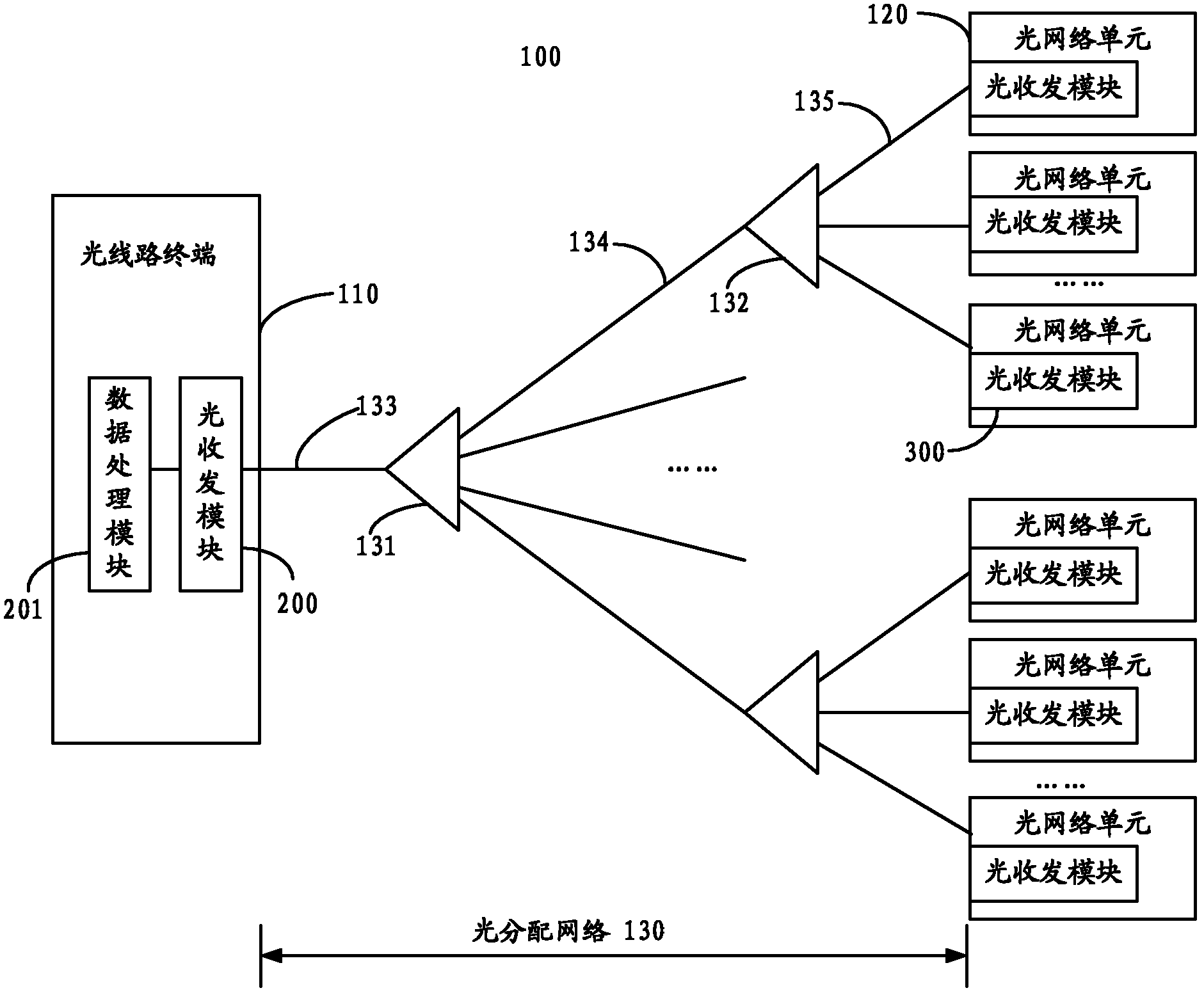
[0023] The optical transceiver module provided in this application can be applied to point-to-multipoint optical fiber networks such as passive optical network systems. see figure 1 , which is a schematic structural diagram of a passive optical network system. The passive optical network system 100 includes at least one optical line terminal 110 , a plurality of optical network units 120 and an optical distribution network 130 . The optical line terminal 110 is connected to the plurality of optical network units 120 through the optical distribution network 130 . Wherein, the direction from the OLT 110 to the ONU 120 is defined as the downlink direction, and the direction from the ONU 120 to the OLU 110 is defined as the uplink direction.

[0024] The passive optical network system 100 may b...


PUM


Abstract

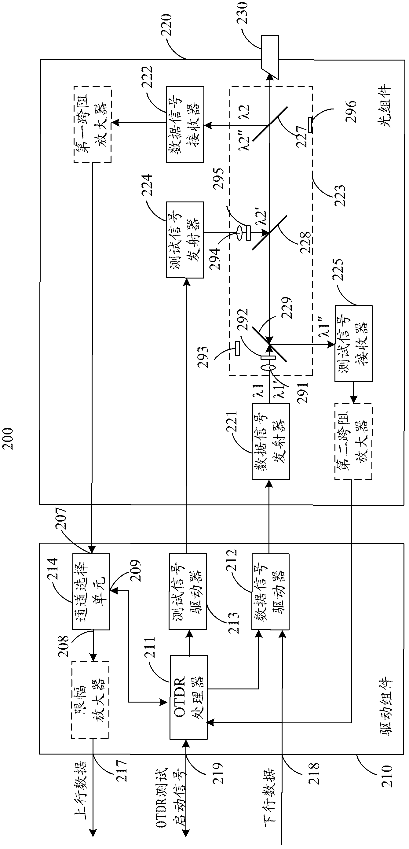
This application provides an optical transceiver module, comprising an optical assembly and a driving assembly connected to the optical assembly. The optical assembly comprises: a data signal transmitter, for transmitting a first data signal with a first wavelength, and transmitting, under the control of the driving assembly, to an optical fiber network a first test signal with the first wavelength; a test signal receiver, for receiving a reflected signal of the first test signal; a test signal transmitter, for transmitting, under the control of the driving assembly, to the optical fiber network a second test signal with a second wavelength; and a data signal receiver, for receiving a second data signal with the second wavelength, and receiving a reflected signal of the second test signal. The application further provides a passive optical network system and device and an optical fiber detection method and system.

Description

technical field [0001] The present application relates to optical communication technology, in particular, to an optical transceiver module with integrated optical fiber detection function and passive optical network (Passive Optical Network, PON) system and equipment, and the present application also relates to a method and system for optical fiber detection . Background technique [0002] With the continuous increase of users' demand for bandwidth, the traditional copper broadband access system is increasingly facing bandwidth bottlenecks; at the same time, the optical fiber communication technology with huge bandwidth capacity is becoming more and more mature, and the application cost is decreasing year by year. The optical fiber access network has become the next A strong competitor of the first-generation broadband access network, especially the passive optical network is more competitive. [0003] Generally speaking, a passive optical network system includes an optica...

Claims


Application Information

Patent Timeline
Patent Type & Authority Applications(China)
IPC IPC(8): H04B10/08H04Q11/00H04B10/077H04B10/40
CPCH04B10/0773H04B10/40
Inventor 殷锦蓉杨素林
Owner HUAWEI TECH CO LTD
Learn More