Soldering device for forming electrical soldering point in magnetic disc driver

A disk drive, welding device technology, applied in the direction of tin feeding device, welding equipment, metal processing, etc., can solve the problems of laser beam energy increase, high energy consumption, etc.

Inactive Publication Date: 2012-10-10
SAE MAGNETICS (HK) LTD
View PDF4 Cites 6 Cited by
  • Summary
  • Abstract
  • Description
  • Claims
  • Application Information

AI Technical Summary

Problems solved by technology

Therefore, the energy of the laser beam is greatly increased, resulting in high energy consumption

Method used


Image

  • Soldering device for forming electrical soldering point in magnetic disc driver
  • Soldering device for forming electrical soldering point in magnetic disc driver
  • Soldering device for forming electrical soldering point in magnetic disc driver

Examples


Embodiment Construction

[0048] Several different preferred embodiments of the present invention will now be described with reference to the accompanying drawings, wherein like reference numerals in different drawings represent like parts. As mentioned above, the essence of the present invention is to provide a soldering device for forming an electrical solder joint in a hard disk drive, the soldering tip device has at least two separate movable shells, so that the size of the soldering tip can control for easy welding.

[0049] refer to Figure 4 , An embodiment of the soldering device 2 of the present invention includes a tip device 20 , a drive device 21 for driving the tip device 20 , a solder ball supply device 22 , a compressed gas supply device 23 and a laser generator 24 . Specifically, the welding tip device 20 has several separate movable shells, so that the size of the welding tip can be adjusted, and the driving device 21 is used to control the movement of the shell of the welding tip dev...


PUM


Abstract

The invention discloses a soldering device for forming an electrical soldering point in a magnetic disc driver. The soldering device comprises a nozzle device, an actuating device, a solder ball feeding device, a pressurized gas feeding device and a laser generator, wherein the nozzle device comprises at least two separated movable casings; a passage is formed by the two casings; an inlet is formed by the upper ends of the two casings; a nozzle is formed by the lower ends of the two casing; the actuating device is connected with the nozzle device, and is used for controlling the two casings of the nozzle device to move close or separate so as to control the inside diameter of the nozzle; the solder ball feeding device is used for delivering a solder ball at the inlet or the nozzle to the passage; the pressurized gas feeding device is used for feeding pressurized gas into the passage to control the falling speed of the solder ball in the passage; and the laser generator is used for emitting laser to the passage so as to melt and return the solder ball. According to the soldering device, the size of the nozzle is controllable, so as to facilitate soldering.

Description

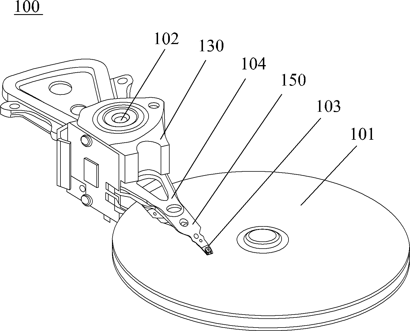
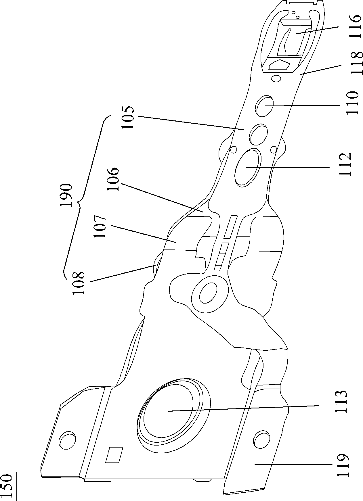
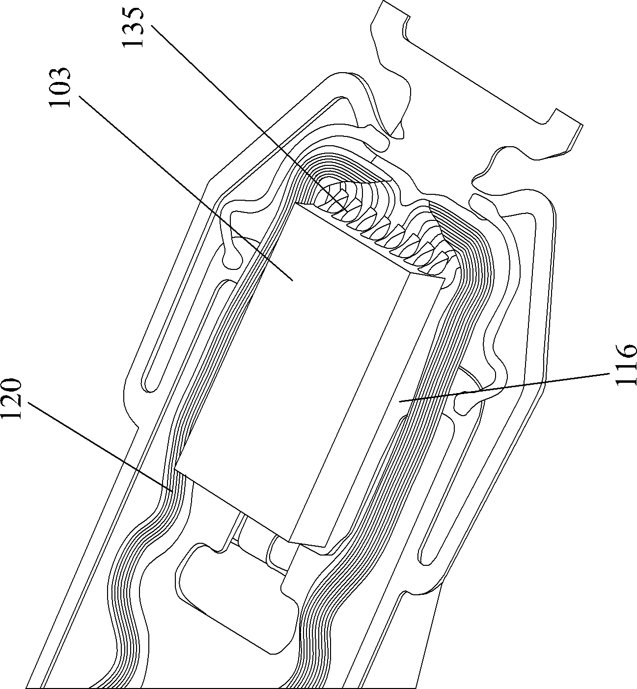
technical field [0001] The present invention relates to soldering devices, and more particularly to a soldering device for forming electrical solder joints in disk drives. Background technique [0002] Hard drives are common information storage devices. Figure 1a is a schematic diagram of a typical hard disk drive 100 . It includes a series of rotatable disks 101 mounted on a spindle motor 102 , and a head stack assembly (HSA) 130 . The HSA 130 includes at least one motor arm 104 and an HGA 150 . [0003] refer to Figure 1b , the HGA 150 includes a magnetic head 103 embedded with a read / write sensor (not shown in the figure) and a suspension member 190 supporting the magnetic head 103 . When the hard disk drive operates, the spindle motor 102 rotates the disk 101 at a high speed, and the magnetic head 103 flies above the disk 101 due to the air pressure generated by the rotation of the disk 101 . The magnetic head 103 moves radially on the surface of the magnetic disk ...

Claims


Application Information

Patent Timeline
Patent Type & Authority Applications(China)
IPC IPC(8): B23K3/00B23K3/06B23K1/005
CPCB23K3/00B23K1/0016B23K3/06B23K1/005B23K3/0623B23K1/0056
Inventor 何耀诚陈灿华卢国洪王宝全
Owner SAE MAGNETICS (HK) LTD
Why Eureka
Try Eureka