Locating mechanism for machining two ends of crank shaft

A technology of positioning mechanism and fixing mechanism, which is applied in the direction of metal processing machinery parts, positioning devices, metal processing equipment, etc., can solve the problems of secondary positioning error, difficulty in crankshaft assembly, and reduction of position accuracy, and achieve convenient operation and simple structure Effect

Active Publication Date: 2014-03-26
长城汽车股份有限公司平湖分公司
View PDF10 Cites 0 Cited by
  • Summary
  • Abstract
  • Description
  • Claims
  • Application Information

AI Technical Summary

Problems solved by technology

After the crankshaft is turned over, it will cause a secondary positioning error, which will affect the position accuracy of the faces at both ends, and the reduced position accuracy will cause difficulty in crankshaft assembly or cause unbalanced crankshaft rotation

Method used


Image

  • Locating mechanism for machining two ends of crank shaft
  • Locating mechanism for machining two ends of crank shaft
  • Locating mechanism for machining two ends of crank shaft

Examples


Embodiment

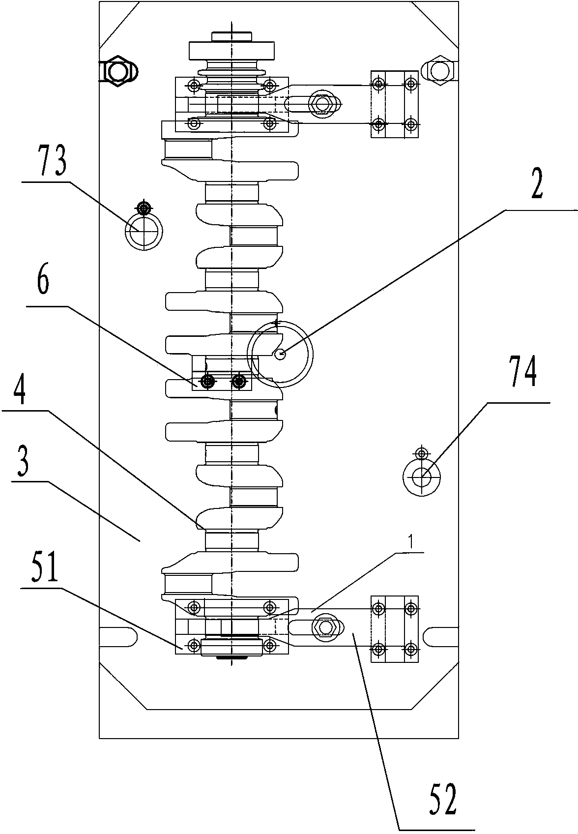
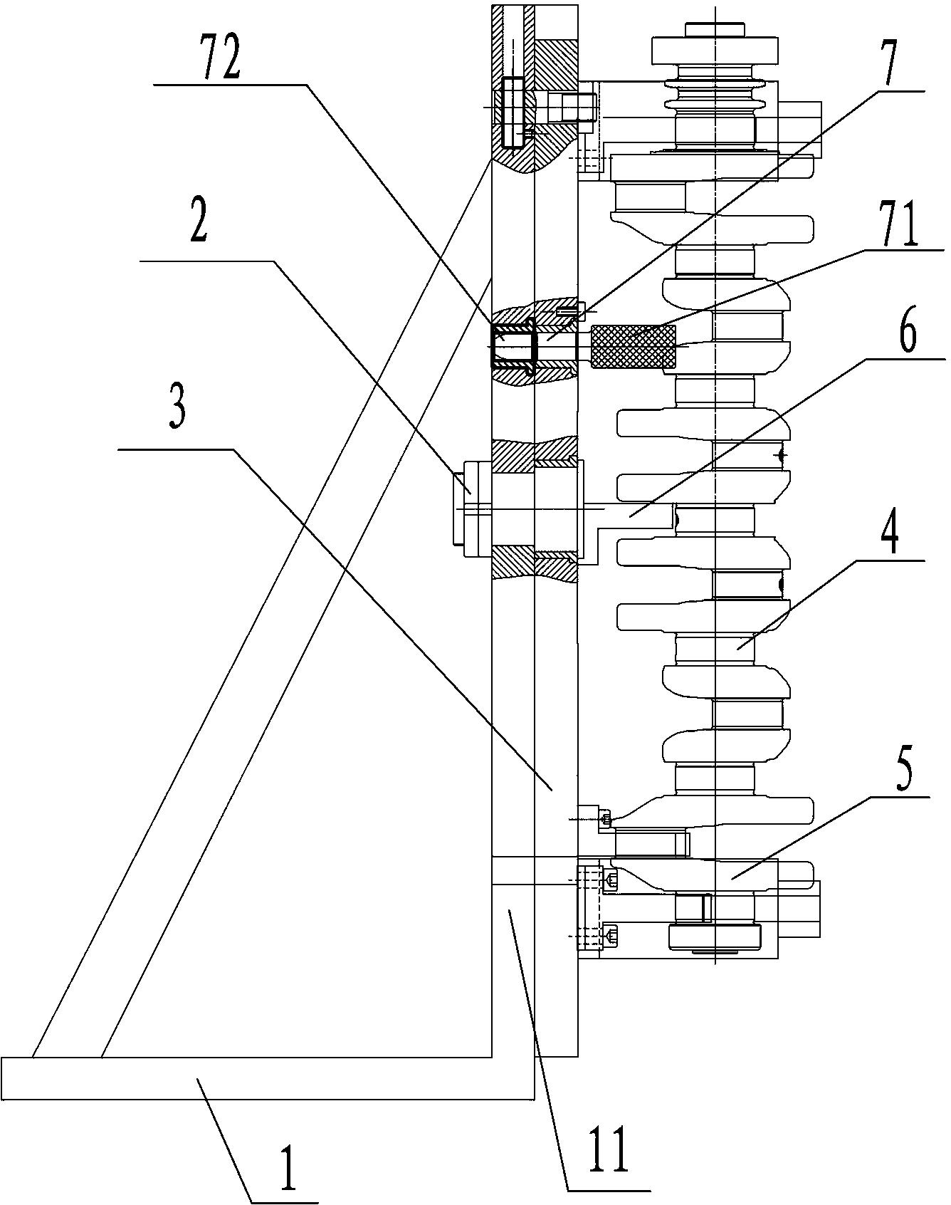
[0038] A processing and positioning mechanism at both ends of a crankshaft, such as figure 1 and figure 2 shown. It includes a support frame 1, a rotating shaft 2, a driven plate 3 and a crankshaft fixing device. in:

[0039] (1) Support frame 1

[0040] The supporting frame 1 is fixed on the ground and has a vertical working surface 11 .

[0041] (2) Rotation axis 2

[0042] The rotating shaft 2 is horizontally arranged in the middle of the working surface 11 of the support frame 1 and can rotate by itself at 360°.

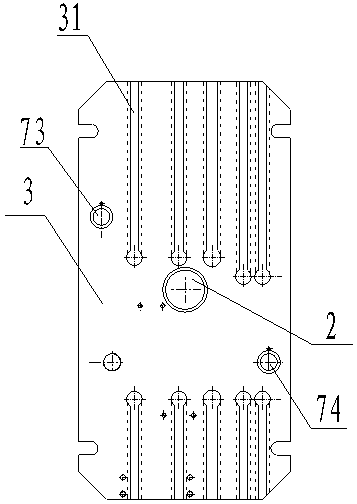
[0043] (3) Follower plate 3

[0044] The driven plate 3 is erected, fixed on the rotating shaft 2 and close to the working surface 11 of the support frame 1, and the working surface 11 of the support frame 1 and the driven plate 3 are fixed by bolts. On the driven plate 3, on the upper and lower sides of the rotating shaft 2, vertically extending height adjustment grooves 31 (such as image 3 shown).

[0045] (4) Crankshaft fixing device

[0046] The c...


PUM


Abstract

The invention discloses a locating mechanism for machining the two ends of a crank shaft, comprising a support frame, a rotating shaft, a driven plate and a crank shaft fixing device, wherein the support frame is fixed on ground and is provided with a vertical working surface; the rotating shaft is horizontally arranged at the middle part of the working surface of the support frame; the driven plate is vertically arranged, is fixed on the rotating shaft and is close to the working surface of the support frame; the driven plate is fixedly provided with a fixing mechanism and an axial locating piece; a driven plate limit mechanism used for fixing the driven plate after the driven plate rotates along with the rotating shaft is arranged between the driven plate and the support frame; and the driven plate is respectively horizontally provided with height regulating slots which extend vertically at the upper side and the lower side of the rotating shaft, and the fixing mechanism and the axial locating piece are both fixed in the height regulating slots. The locating mechanism disclosed by the invention is used for locating in the machining of the two ends of the crank shaft, holes at the two ends can be machined while the crank shaft is clamped once, and therefore positional accuracy of the holes at the two ends is guaranteed and labour intensity of operating personnel is reduced.

Description

technical field [0001] The invention relates to a machined positioning mechanism, in particular to a machined positioning mechanism at both ends of a crankshaft that can precisely position the center holes or bolt holes on both ends of the crankshaft. Background technique [0002] The crankshaft is an important transmission part of the engine. If the crankshaft rotates unbalanced when the engine is working, it will cause the engine to vibrate and other phenomena. Therefore, it is necessary to ensure that the center holes on both ends of the crankshaft are concentric and the position accuracy of the bolt holes and signal mounting holes. [0003] In the prior art, when machining the center holes or bolt holes on both ends of the crankshaft, the machining tool can only process one end of the crankshaft first, and then the other end can be processed after the crankshaft is turned over and re-clamped and positioned. After the crankshaft is overturned, it will cause a secondary po...

Claims


Application Information

Patent Timeline
Patent Type & Authority Patents(China)
IPC IPC(8): B23Q3/00
Inventor 栗云龙
Owner 长城汽车股份有限公司平湖分公司
Why Eureka
Try Eureka