
A fully automatic mobile articulated mine stone cutter

A mobile and articulated technology, applied in the field of mining stone cutters, can solve the problems of low cutting efficiency and waste, and achieve the effect of easy command and operation

Inactive Publication Date: 2015-10-21
吴晓骥
View PDF9 Cites 0 Cited by
  • Summary
  • Abstract
  • Description
  • Claims
  • Application Information

AI Technical Summary

Problems solved by technology

[0002] Most of the existing mine stone cutters are composed of cutting head, saw blade, wheel, guide rail and frame base, etc. The cutting head is installed on the guide rail through the wheel. When cutting stone, the general cutting head only drives the saw blade Rotating at high speed, the guide rail is fixed on the stone, and the cutting head moves along the guide rail to cut. This cutting method needs to re-arrange the guide rail when cutting a stone after cutting the next stone, and the cutting efficiency is extremely low. In addition , the cutting of stone by this mine stone cutter is limited by the stroke of the cutting head and guide rail, and some corners of the ore are also difficult to be cut, resulting in waste

Method used


Image

  • A fully automatic mobile articulated mine stone cutter
  • A fully automatic mobile articulated mine stone cutter
  • A fully automatic mobile articulated mine stone cutter

Examples


Embodiment 1

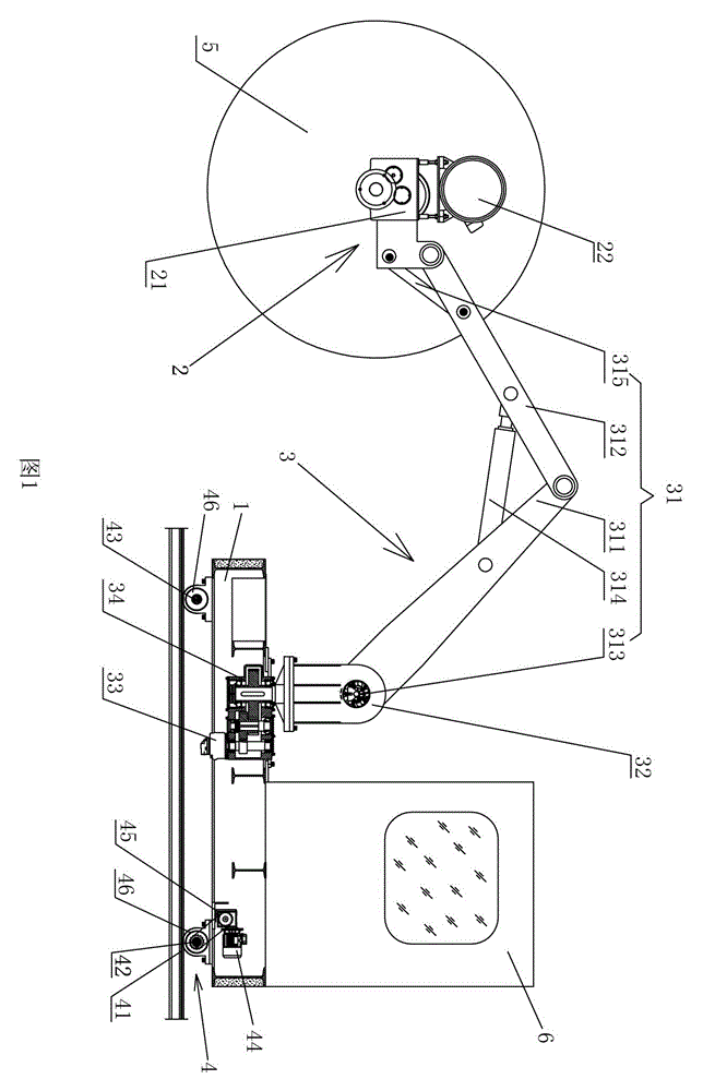
[0025] Refer to attached figure 1 . A fully automatic mobile articulated rock cutter, comprising a base 1, a cutting head 2, an operating room 6, a transmission support mechanism 3 for driving the rotation of the cutting head 2, and a walking mechanism 4 for moving the base, the transmission support One end of the mechanism 3 is installed on the base 1 and can rotate around a vertical axis of the plane defined by the base 1. The other end of the transmission support mechanism 3 is rotatably connected with the cutting head 2, which is installed on the cutting head 2. There is a cutting blade 5 for cutting ore, and the traveling mechanism 4 is installed on the bottom of the base 1 . The operating room 6 is fixed on the base 1 .

[0026] Refer to attached figure 1 . The transmission support mechanism 3 includes a manipulator 31, a rotating base 32, and a rotating base rotating hydraulic motor 33 for driving the rotating base 32 to rotate. The bottom of the rotating base 32 is...

Embodiment 2

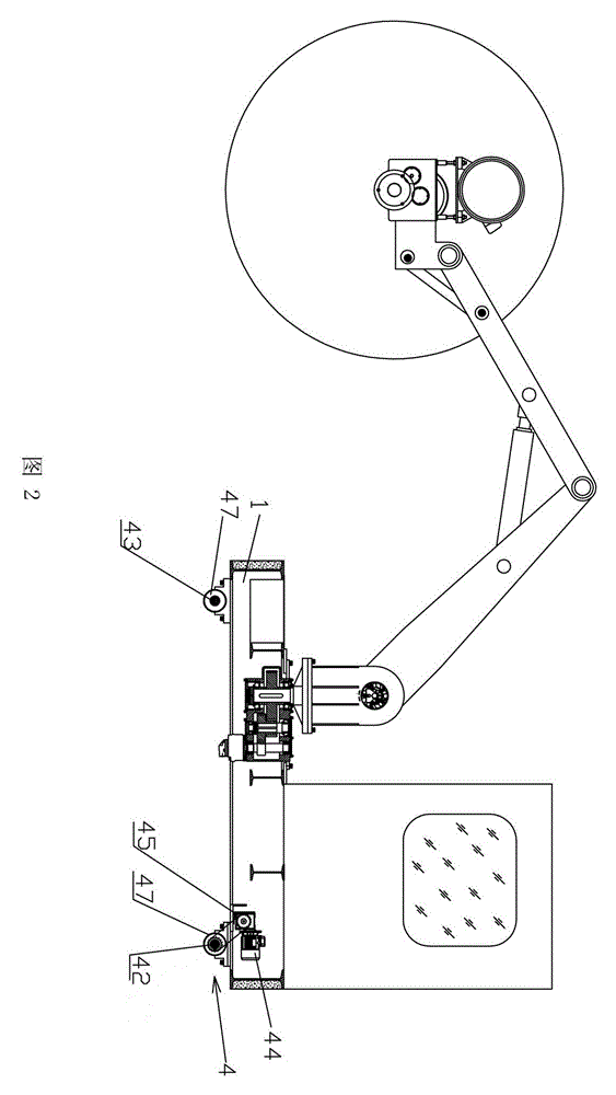
[0031] Refer to attached figure 2 . The embodiment of this embodiment is basically the same as that of Embodiment 1, the difference is that the traveling mechanism 4 includes a moving main shaft 42 and a moving auxiliary shaft 43 respectively installed on the rear bottom of the base 1 and the front bottom of the base 1 and used for Drive the drive motor 44 that moves the main shaft to rotate, the drive motor 44 is connected to the mobile main shaft 42 through a speed reducer 45, and the two ends of the mobile main shaft 42 and the mobile sub-shaft 43 are respectively equipped with wheels 47 for moving the base 1 .

Embodiment 3

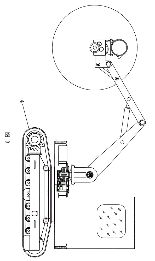
[0033] Refer to attached image 3 . The embodiment of this embodiment is basically the same as that of the first embodiment, the difference is that: the running mechanism 4 is a crawler belt, and the walking mode of the crawler belt is the prior art, and its running principle will not be described in detail here.


PUM


Abstract

The invention relates to a fully-automatic mobile joint type stone cutting machine for mines. The fully-automatic mobile joint type stone cutting machine comprises a base, a cutting machine head, a transmission and supporting mechanism and a traveling mechanism, wherein the transmission and supporting mechanism is used for driving the cutting machine head to rotate, and the traveling mechanism is used for moving the base; one end of the transmission and supporting mechanism is rotatably mounted on the base; the other end of the transmission and supporting mechanism is movably connected with the cutting machine head; a cutting sheet, which is used for cutting ores, is mounted on the cutting machine head; and the traveling mechanism is mounted at the bottom of the base. According to the fully-automatic mobile joint type stone cutting machine for the mines, the design is reasonable, and the cutting machine head can rotate under the drive of the transmission and supporting mechanism, can cut the ores along any angular direction under the condition that the stone cutting machine is not moved, and can continuously cut a next piece of ore without rearranging guide rails after one piece of ore is cut, so that the cutting efficiency is increased.

Description

technical field [0001] The invention relates to a mine stone cutter, in particular to a fully automatic movable articulated mine stone cutter. Background technique [0002] Most of the existing mine stone cutters are composed of cutting head, saw blade, wheel, guide rail and frame base, etc. The cutting head is installed on the guide rail through the wheel. When cutting stone, the general cutting head only drives the saw blade Rotating at high speed, the guide rail is fixed on the stone, and the cutting head moves along the guide rail to cut. This cutting method needs to re-arrange the guide rail when cutting a stone after cutting the next stone, and the cutting efficiency is extremely low. In addition The cutting of stone by this kind of mining stone cutter is limited by the stroke of the cutting head and guide rail, and some corners of the ore are also difficult to be cut, resulting in waste. Contents of the invention [0003] The purpose of the present invention is to ...

Claims


Application Information

Patent Timeline
Patent Type & Authority Patents(China)
IPC IPC(8): B28D1/24
Inventor 吴晓骥
Owner 吴晓骥
Learn More