Vehicle kinetic energy recovery device

A kinetic energy recovery, vehicle technology, applied in auxiliary drive devices, control devices, vehicle components, etc., can solve the problem of waste of inertial kinetic energy, and achieve the effect of reducing the rotational speed

Active Publication Date: 2015-05-13
张怀
View PDF5 Cites 0 Cited by
  • Summary
  • Abstract
  • Description
  • Claims
  • Application Information

AI Technical Summary

Problems solved by technology

[0002] Low-carbon environmental protection, energy saving and emission reduction are what all countries in the world are trying to do, and automobile exhaust emissions are a problem that every country faces. Various automobile companies have also made corresponding achievements in this regard. However, when the car brakes, the inertial kinetic energy of the car is wasted. How to use the inertial kinetic energy when the car brakes is a problem that people are studying.

Method used


Image

  • Vehicle kinetic energy recovery device
  • Vehicle kinetic energy recovery device
  • Vehicle kinetic energy recovery device

Examples


Embodiment 1

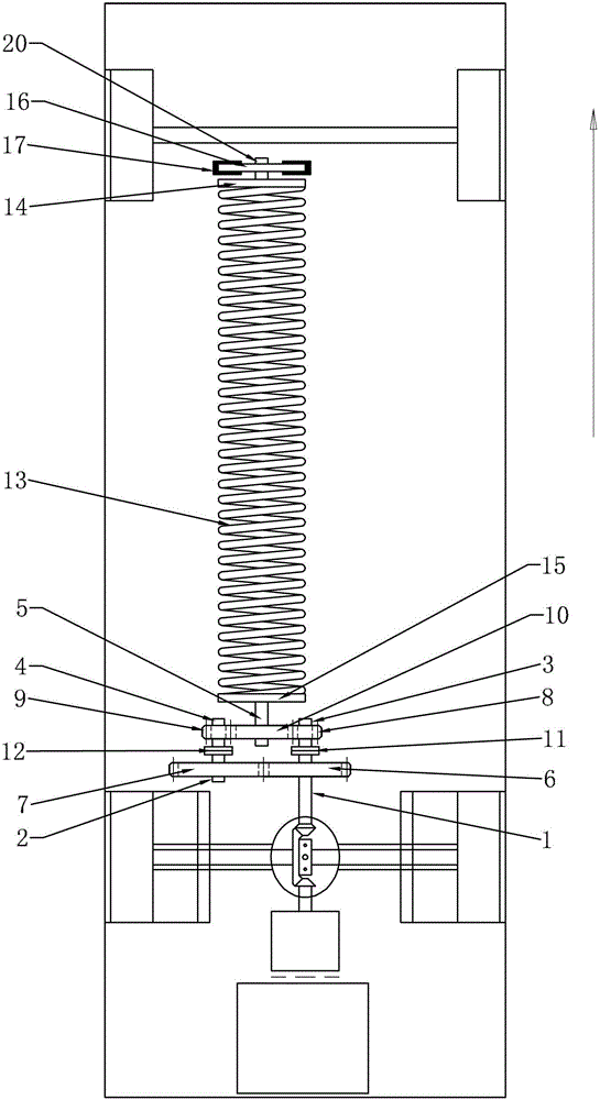
[0016] like figure 1 As shown, the vehicle kinetic energy recovery device of the present invention includes a kinetic energy recovery mechanism and a kinetic energy storage mechanism.

[0017] The kinetic energy recovery mechanism includes a first shaft 1, a first gear 6, a second shaft 2, a second gear 7, a third shaft 3, a third gear 8, a fourth shaft 4, a fourth gear 9, a fifth shaft 5, a To the gear 10, the first clutch 11 and the second clutch 12, the first, second, third, fourth and fifth rotating shafts 1, 2, 3, 4, 5 are all rotated and installed on the chassis, and the installation method is that each rotating shaft It can be installed on the vehicle chassis through the bearing, and can also be installed on the housing through the bearing, and then the housing is fixedly installed on the vehicle chassis. The first gear 6 is fixedly mounted on the first shaft 1, the second gear 7 is fixedly mounted on the second shaft 2, the third gear 8 is fixedly mounted on the third...

Embodiment 2

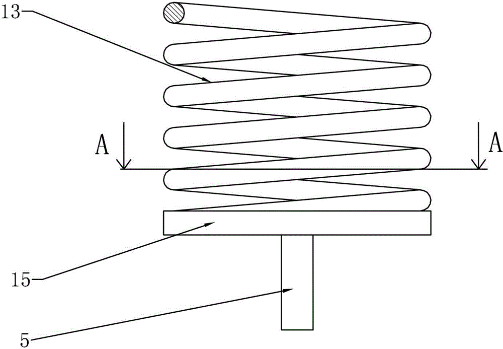
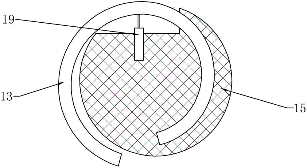
[0021] like Figure 4 As shown, the only difference between this embodiment and Embodiment 1 is that the reversing gear 10 is arranged between the first gear 6 and the second gear 7, and the reversing gear 10 is simultaneously connected with the first gear 6 and the second gear 7 The third gear 8 and the fourth gear 9 are directly meshed, the second spring fixed plate 15 is fixedly connected with the fourth shaft 4, and can also be fixedly connected with the third shaft 3, the number of teeth of the fourth gear 9 is greater than that of the third gear 8 number of teeth, between the first spring fixed disk 14 and the second spring fixed disk 15, a support shaft 18 is also provided, one end of the support shaft 18 is fixedly connected with the first spring fixed disk 14, and the other end of the support shaft 18 is connected with the second spring fixed disk 15. The spring fixing plate 15 is fixedly connected, and the spring 13 is sleeved on the support shaft 18 . By providing ...


PUM


Abstract

The invention provides a vehicle kinetic energy recovery device and relates to a device which can recover and store vehicle kinetic energy and release the kinetic energy again when the kinetic energy is required. The vehicle kinetic energy recovery device comprises a kinetic energy recovery mechanism and a kinetic energy storage mechanism, one end of a first revolving shaft of the kinetic energy recovery mechanism is connected with a transmission shaft of a vehicle main speed reducer through a bevel gear, the other end of the first revolving shaft is connected with a third revolving shaft through a first clutch, a second revolving shaft is connected with a fourth revolving shaft through a second clutch, gears of the first revolving shaft and the second revolving shaft are meshed with each other, and gears of the third revolving shaft, the fourth revolving shaft and a fifth revolving shaft are meshed mutually and sequentially. A first spring fixing disk and a second spring fixing disk of the kinetic energy storage mechanism are respectively and fixedly installed at two ends of a spring, the first spring fixing disk is fixedly connected with a brake disk, and the second spring fixing disk is fixedly connected with the fourth revolving shaft. The vehicle kinetic energy recovery device can store the vehicle kinetic energy during deceleration and release the stored kinetic energy again when a vehicle is started.

Description

technical field [0001] The invention relates to an auxiliary driving device for an automobile, in particular to a device which recycles and stores the kinetic energy of the running vehicle and releases the kinetic energy again when needed. Background technique [0002] Low-carbon environmental protection, energy saving and emission reduction are what all countries in the world are trying to do, and automobile exhaust emissions are a problem that every country faces. Various automobile companies have also made corresponding achievements in this regard. However, when the car brakes, the inertial kinetic energy of the car is wasted. How to use the inertial kinetic energy when the car brakes is a problem that people are studying. Contents of the invention [0003] The technical problem to be solved by the present invention is to provide a vehicle kinetic energy recovery device with simple structure and easy operation, which can store the kinetic energy of the vehicle when brak...

Claims


Application Information

Patent Timeline
Patent Type & Authority Patents(China)
IPC IPC(8): B60K25/10
Inventor 张怀
Owner 张怀
Why Eureka
Try Eureka