
Steam turbine rotor

A steam turbine rotor and impeller technology, applied in mechanical equipment, engine components, machines/engines, etc., can solve the problems of reducing the strength of the main shaft and impeller, difficult assembly, low assembly efficiency, etc., to prevent loosening and sliding, low production cost, The effect of high production efficiency

Active Publication Date: 2014-09-03
DONGFANG TURBINE CO LTD
View PDF5 Cites 0 Cited by
  • Summary
  • Abstract
  • Description
  • Claims
  • Application Information

AI Technical Summary

Problems solved by technology

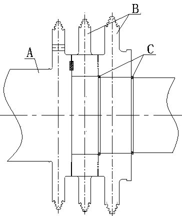
This method has the following main defects: 1. It is necessary to process the assembly grooves of the positioning keys on the end faces of the outer assembly surfaces of all levels on the main shaft and the end surfaces of the inner assembly surfaces of the impellers at all levels, which directly increases the processing difficulty of the main shaft and impellers, seriously The processing efficiency of the main shaft and impeller is affected, and the production cost of the enterprise is high; 2. The assembly groove of the positioning key is bound to cause damage to the stress of the main shaft and the impeller, thereby reducing the strength of the main shaft and the impeller; 3. The assembly parts of the rotor increase, further Increase the production cost of the enterprise; 4. The assembly relationship of the rotor is complicated, the assembly efficiency is low, and the assembly requirements are strict (especially the assembly clearance requirements), and the assembly is difficult; 5. The firmness and reliability of the assembly are poor, and it is loose on the main shaft After the impeller is affected by the steam force, it will slide axially. Although the positioning key can stop it, it is very limited, and the sliding impeller can easily cut off the positioning key, which still poses a great safety hazard.

Method used


Image

  • Steam turbine rotor
  • Steam turbine rotor
  • Steam turbine rotor

Examples


Embodiment 1

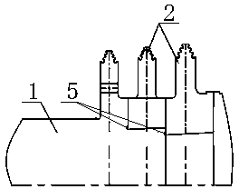
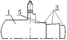
[0018] see figure 2 , image 3 and Figure 4 : The present invention comprises a main shaft 1 and impellers 2 of various levels, and the main shaft 1 and impellers 2 of various levels are set structures. Among them, the outer surface of the main shaft 1 is processed with the outer assembly surface 3 for assembling the impellers 2 of each level. The outer assembly surfaces 3 of each level have tapers respectively. The taper of the outer assembly surfaces 3 of each level is 1:60 respectively. The root of the surface 3 is provided with a concave chamfered stress groove 5, and the outer surface of the main shaft 1 is stepped. The impellers 2 of each stage have ring-shaped internal assembly surfaces 4 respectively, and the internal assembly surfaces 4 also have tapers. After being heated, the first-stage impeller 2 is assembled on the corresponding outer assembly surface 3 of the main shaft 1 through its own inner assembly surface 4, and the cooled impellers 2 of each stage and...

Embodiment 2

[0020] The other structures of this embodiment are the same as those of Embodiment 1, except that the taper of the outer assembly surface on the main shaft is 1:85 respectively.

Embodiment 3

[0022] The other structures of this embodiment are the same as those of Embodiment 1, except that the taper of the outer assembly surface on the main shaft is 1:66 respectively.


PUM


Abstract

The invention discloses a steam turbine rotor, which includes a main shaft and impellers of various levels. The main shaft and impellers of all levels are in a set structure. The outer surface of the main shaft is provided with an outer assembly surface for assembling the impellers of various levels. The impellers of each level are assembled on the corresponding outer assembly surface of the main shaft through their own annular inner assembly surfaces; the outer assembly surfaces of each level on the main shaft have a certain taper; the inner assembly surfaces of the impellers of each level have corresponding The outer assembly surface of the impeller and the main shaft at all levels are matched with each other, and the taper is consistent. The main shaft and the impeller of the present invention are assembled with a conical surface, and the impeller realizes an inverted self-locking on the main shaft, and the assembly is firm and reliable, which effectively prevents the impeller from loosening and sliding from the main shaft, and does not require positioning keys for positioning and locking. All the disadvantages caused by the positioning key, the production cost can be effectively controlled, the safety of the rotor is high, and the service life is long.

Description

technical field [0001] The invention relates to a steam turbine, in particular to a steam turbine rotor. Background technique [0002] The steam turbine rotor is the general term for the rotating part of the steam turbine, which is used to collect the mechanical energy obtained from the moving blade cascades at all levels and transmit the mechanical energy to the generator rotor. According to the combination of main shaft and impeller, the existing steam turbine rotors are divided into integral forged rotors, sleeved rotors, welded rotors and combined rotors. Among them, the sleeved rotors are easy to forge, easy to process and short in processing cycle. Medium and low voltage parts have been widely used. [0003] see figure 1 : The conventional packaged rotor includes the main shaft A and impellers B at all levels. The outer surface of the main shaft A is provided with an outer assembly surface for assembling the impellers B at each level. The outer assembly surface is a ...

Claims


Application Information

Patent Timeline
Patent Type & Authority Patents(China)
IPC IPC(8): F01D5/06
Inventor 张晓东杨灵袁永强王鑫王建伟
Owner DONGFANG TURBINE CO LTD
Learn More