
Automated mechanical transmission

A kind of automatic transmission, mechanical technology, applied in the direction of automatic clutch, mechanical equipment, transmission box, etc., can solve the problems of short service life, poor sensitivity, adverse effects of fuel consumption, etc., and achieve the effect of avoiding complex structure and good fuel saving effect

Inactive Publication Date: 2012-10-10
黄兆焕
View PDF8 Cites 3 Cited by
  • Summary
  • Abstract
  • Description
  • Claims
  • Application Information

AI Technical Summary

Benefits of technology

This patented technology uses an improved mechanism for transmitting data between two parts that rotate smoothly at different speeds without being affected by external factors like weather conditions. By utilizing this system, vehicles have more efficient energy use compared to traditional methods involving electronic control systems. Additionally, there're no complicated structures needed due to its simplicity and quicker switching from one mode to another.

Problems solved by technology

The technical problem addressed by this patented technology relates to improving the efficiency and performance of power transmitting systems (PTS) with electronic controls. Specifically, current methods are limited in their ability to adapt to different terrains based solely upon driver's needs without sacrificing safety factors like responsiveness and durability. This results in reduced fuel economy compared to traditional hydraulic transmission systems while also requiring more frequent maintenance.

Method used


Image

  • Automated mechanical transmission
  • Automated mechanical transmission

Examples


Embodiment Construction

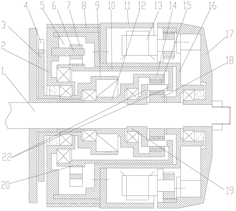
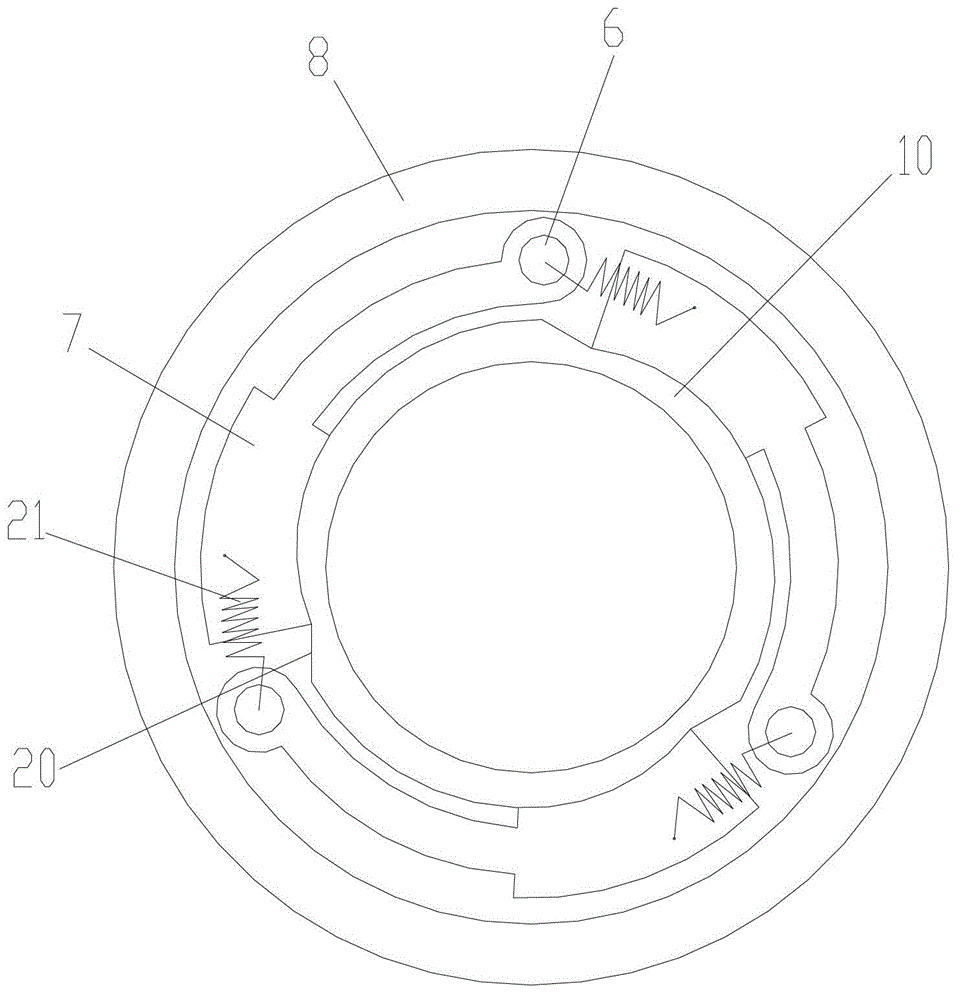
[0015] figure 1 It is a structural schematic diagram of the present invention, figure 2 It is a structural schematic diagram of the torque clutch of the present invention, as shown in the figure: the mechanical automatic transmission of this embodiment includes a power input member 8, a slow gear transmission assembly, a centrifugal clutch 13 and a power output member 1, and the power input member 8 passes through The centrifugal clutch 13 transmits power to the power output member 1, and the centrifugal clutch 13 is used for clutching and disconnecting between the power input member 8 and the power output member 1 when the rotational speed of the power output member 1 is lower than or reaches a set value. Open or engage to transmit fast gear power, forming the first fast gear transmission route; the power input member 8 also transmits the slow gear power to the power output member 1 through the slow gear transmission assembly in a manner that can be overtaken by the fast gea...


PUM


Abstract

The invention discloses an automated mechanical transmission. A power input part transmits power to a power output part through a centrifugal clutch, and the centrifugal clutch engages and disengages when speed of the power output part is lower than or reaches a set value and is used for stopping or allowing for high-gear power transmission between the power input part and the power output part. The power input part further transmits low-gear power to the power output part through a low-gear transmission component in such way that low gear can be exceeded by high gear. When the speed of the power output part reaches the set value, the centrifugal clutch meshes to transmit power at the high gear under the speed. When resistance is high, the centrifugal clutch disengages to transmit power at the low gear as the power output part decreases in speed. Therefore, the automated mechanical transmission automatically sets a start gear when a vehicle starts on the flat ground, downhill or uphill, and is timely and direct. The automated mechanical transmission quickly switches to the high gear when running resistance in flat ground start and the like is low, and accordingly is effective in energy conservation and consumption reduction.

Description


Claims


Application Information

Patent Timeline
Owner 黄兆焕
Learn More