
Projecting lamp

A technology for floodlights and lamp housings, applied in the field of floodlights, can solve the problems of unstable emitted light, untimely maintenance, slow startup, etc., so as to reduce the aging speed and the probability of other failures, facilitate installation and maintenance, increase The effect of anti-vibration performance

Inactive Publication Date: 2012-10-10
OCEANS KING LIGHTING SCI&TECH CO LTD +1
View PDF9 Cites 4 Cited by
  • Summary
  • Abstract
  • Description
  • Claims
  • Application Information

AI Technical Summary

Problems solved by technology

[0003] Existing LED floodlights generally use gas discharge lamps as the light source, and the service life of the bulbs is short, which brings the inconvenience of frequent replacement of bulbs, especially for outdoor large-area unattended lighting, which can easily lead to untimely maintenance and unavailable Appropriate lighting effects
At the same time, this kind of gas discharge lamp starts slowly, and the power of the lamp is often very large. It not only consumes a lot of power during operation, which is not conducive to energy saving, but also generates a lot of heat. Often due to the poor heat dissipation effect, the lamp cannot be used in actual use. The medium light decay is serious, and it is also prone to stroboscopic phenomena, and the lighting effect of the emitted light is not ideal; moreover, due to the high temperature of the lamp, it also accelerates the aging rate of each component, making the actual service life of the lamp not long; in addition, The joints of the parts of the existing floodlights are generally rigidly connected, and their applicability is not strong. When used in places with strong vibrations, the emitted light is unstable, and shaking will occur, which will affect the lighting effect of the lamps.

Method used


Image

  • Projecting lamp
  • Projecting lamp
  • Projecting lamp

Examples


Embodiment Construction

[0025] In order to make the technical problems, technical solutions and beneficial effects to be solved by the present invention clearer, the present invention will be further described in detail below in conjunction with the accompanying drawings and embodiments. It should be understood that the specific embodiments described here are only used to explain the present invention, not to limit the present invention.

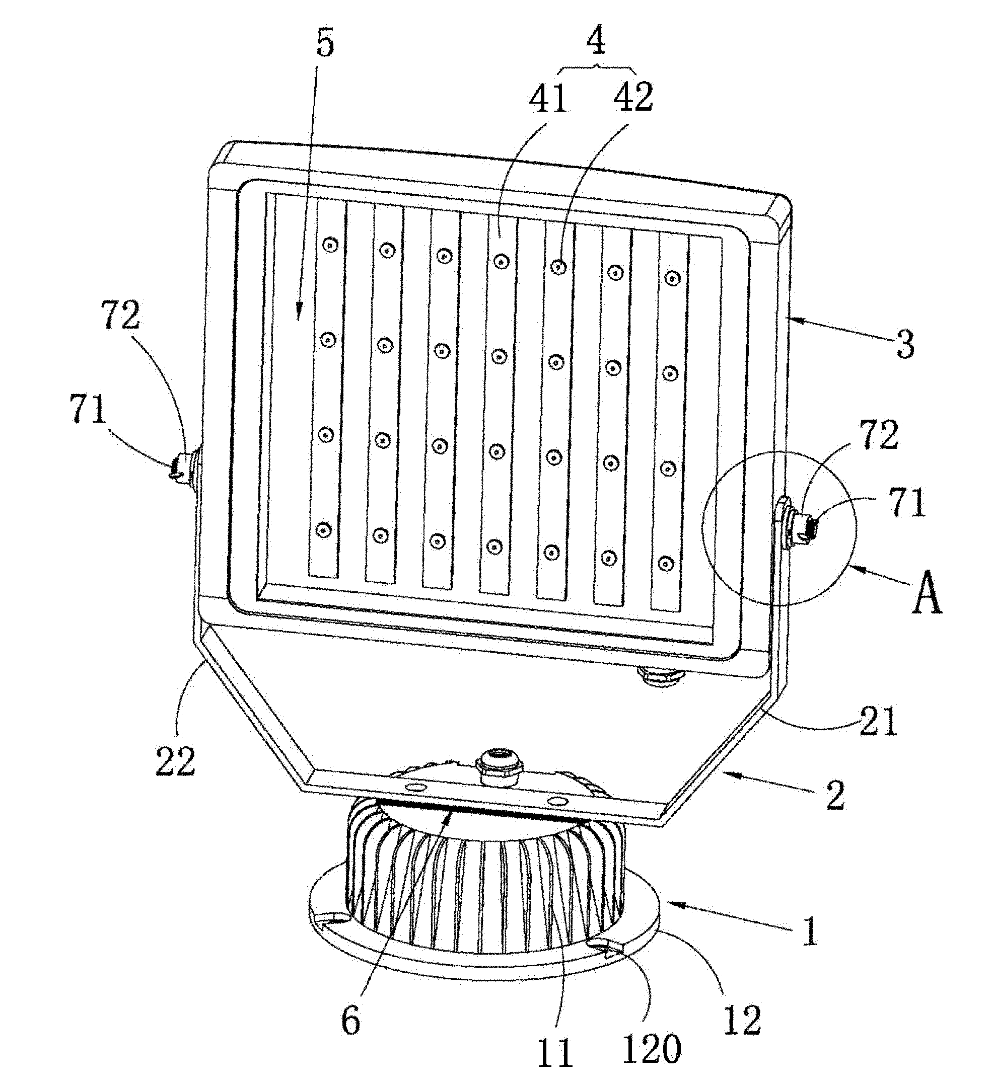
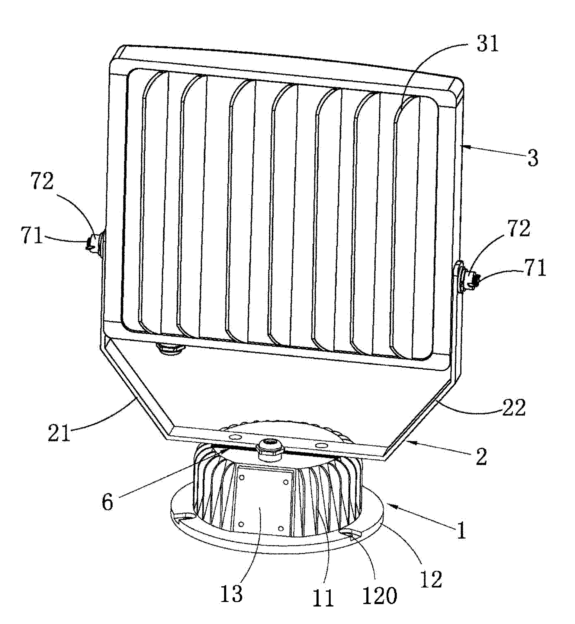
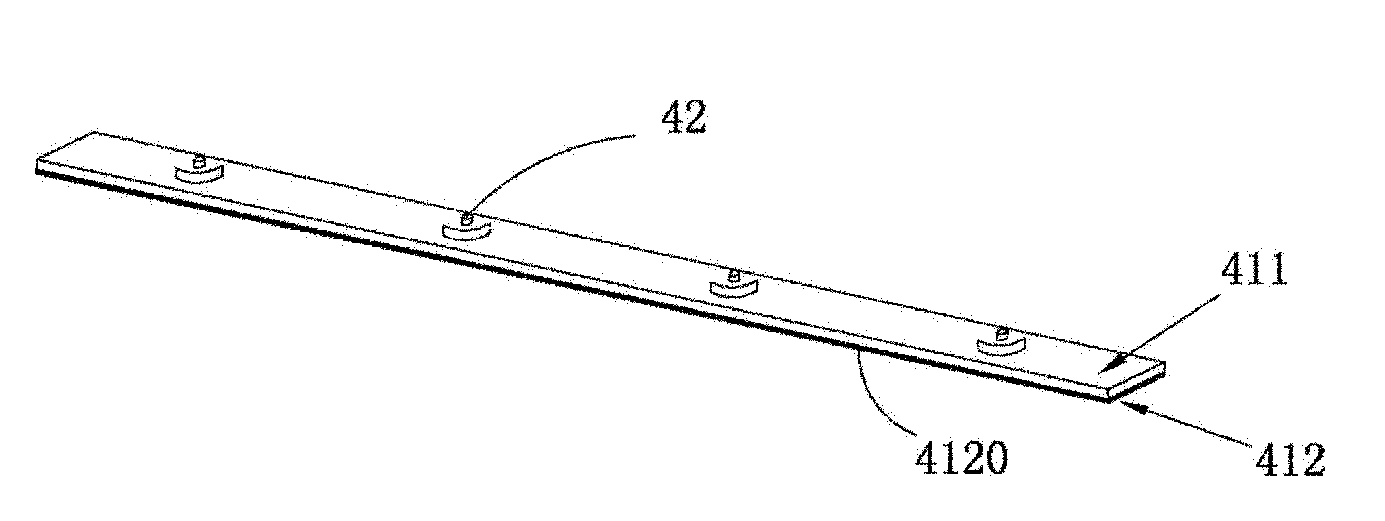
[0026] Please also refer to Figure 1 to Figure 3 , which is a schematic diagram of the three-dimensional structure of the floodlight provided by the present invention, will now be described. The floodlight includes a base 1, a light source bracket 2 arranged on the base 1, a lamp housing 3 hinged on both sides on the light source bracket, and an LED arranged in the lamp housing 3 The light source assembly 4 and a transparent light-emitting lens 5 arranged on the lamp housing 3; also includes: a light source driver (not visible in the figure, not shown) arranged i...


PUM


Abstract

The invention is applicable for the field of lighting technology, and provides a projecting lamp, comprising a base, a light source support disposed on the base, a lamp shell with two sides hinged to the light source support, LED light source components disposed in the lamp shell, and a transparent emergent light lens disposed on the lamp shell. The projecting lamp is characterized in that the projecting lamp also comprises a light source driving element disposed in a cavity of the base; the LED light source component includes a plurality of LED aluminium substrates fixed on the lamp shell and a plurality of LED lamp beads disposed on the aluminium substrates; each LED aluminium substrate has a first face and a second face, the LED lamp beads are disposed on the first face of the LED aluminium substrate, and a layer of copper foil is arranged on the second face of the LED aluminium substrate; and a plurality of radiating ribs are disposed on the shell. The projecting lamp provided in the invention has advantages of good radiating capability and anti-vibration capability, high luminous efficiency, low power consumption, long service life, and easy installation and maintenance.

Description

technical field [0001] The invention belongs to the technical field of lighting, and more specifically relates to a floodlight. Background technique [0002] Floodlights are lamps whose illuminance on the specified illuminated surface is higher than that of the surrounding environment, also known as spotlights. Generally, it is capable of aiming in any direction and has a structure that is not affected by climatic conditions. It is mainly used for large-area mines, building outlines, interior and exterior lighting of buildings, indoor partial lighting, billboard lighting, stadiums, overpasses, monuments, parks and flower beds, landscape lighting, medical culture and other special facilities lighting, bars, Entertainment venues such as dance halls are also used as mood lighting. Therefore, almost all large-area lighting fixtures used outdoors can be regarded as floodlights. The output beam angle of the floodlight can be wide or narrow, and the range of variation is between...

Claims


Application Information

Patent Timeline
IPC IPC(8): F21S2/00F21V29/00F21V15/00F21V31/04F21V19/00F21V17/10F21V5/04F21Y101/02F21K9/20F21V29/77F21V29/89F21Y115/10
Inventor 周明杰冷华
Owner OCEANS KING LIGHTING SCI&TECH CO LTD
Learn More