Light-emitting device and projection system and stage lighting system thereof

A technology of light-emitting device and light-splitting device, which is applied to projection devices, lighting devices, fixed lighting devices, etc., can solve the problems of different excited light intensity, uneven concentration, uneven thickness of phosphor layer, etc., and achieve the improvement of flickering phenomenon. Effect

Active Publication Date: 2012-10-10
APPOTRONICS CORP LTD
View PDF5 Cites 25 Cited by
  • Summary
  • Abstract
  • Description
  • Claims
  • Application Information

AI Technical Summary

Problems solved by technology

However, due to the deviation of the drive control itself, and the rotational angular velocity of the drive device cannot be kept absolutely stable, the rotation cycle of the first drive device and the rotation cycle of the second drive device cannot be completely synchronized, but there are often fluctuations. small difference
On the other hand, the current phosphor layer molding technology is not perfect, and the phosphor layer after molding often has problems such as uneven thickness, uneven concentration, or unevenness on the surface, which makes different positions of the phosphor layer excited. The intensity of light varies
Therefore, when there is a slight difference between the rotation period of the fluorescent color wheel and the rotation period of the spectroscopic color wheel, the rotation of the fluorescent pink wheel and the rotation of the spectroscopic color wheel will produce a beat frequency phenomenon, and the frequency of the beat frequency phenomenon is very low. The brightness change frequency of the outgoing light of the spectroscopic device is relatively low, so that the human eye can easily perceive the flickering phenomenon of the outgoing light

Method used


Image

  • Light-emitting device and projection system and stage lighting system thereof
  • Light-emitting device and projection system and stage lighting system thereof
  • Light-emitting device and projection system and stage lighting system thereof

Examples


Embodiment 1

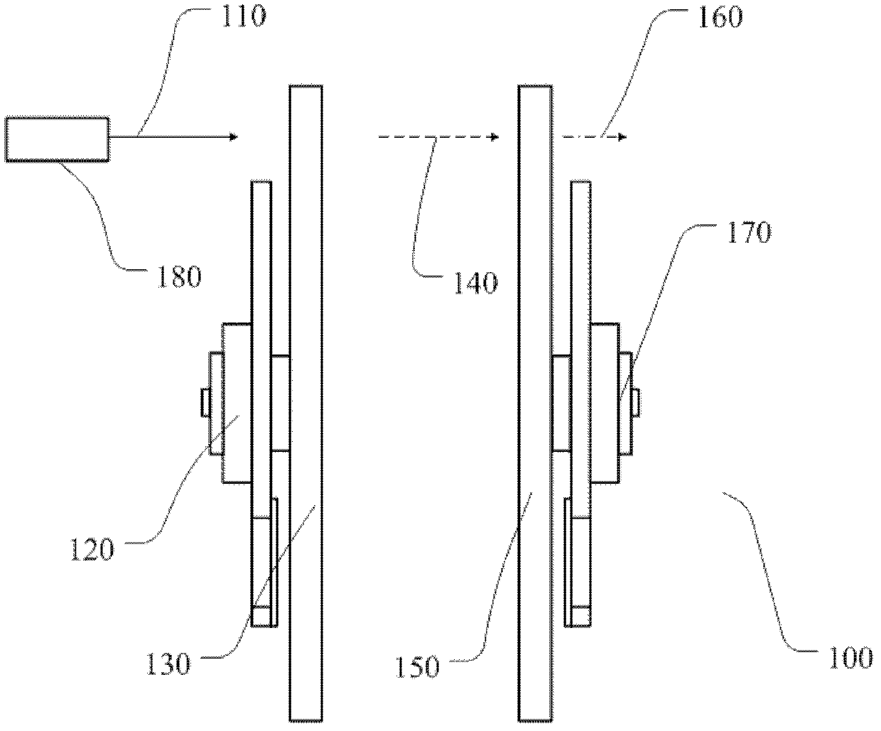
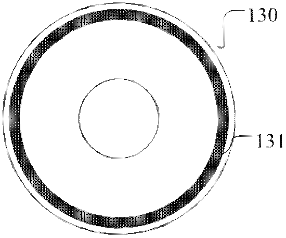
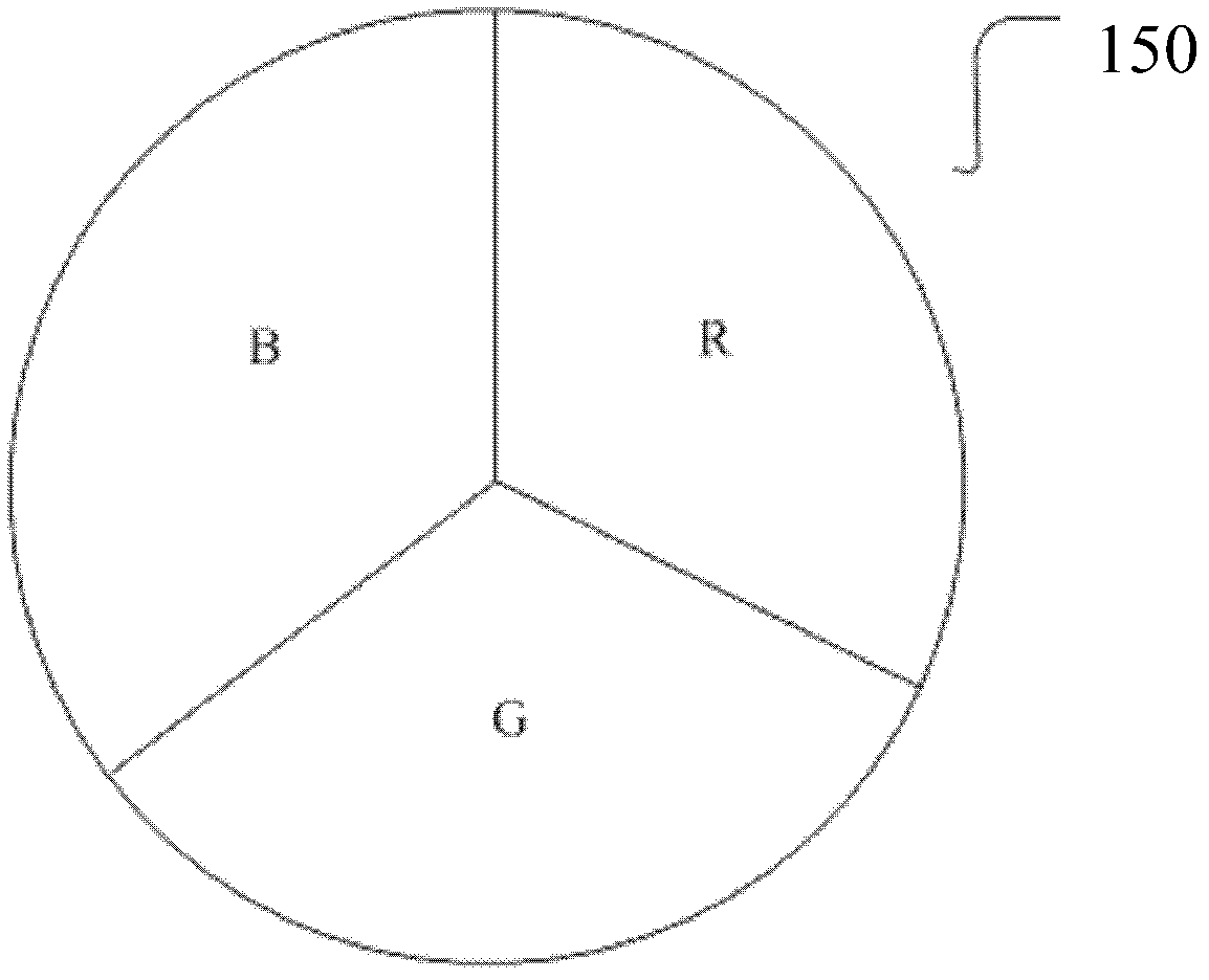
[0035] Figure 2a The structure diagram of the light emitting device shown is the first embodiment of the present invention. The light emitting device 200 includes an excitation light source 280 , a wavelength converting device 230 , a first driving device 220 , a spectroscopic device 250 , and a second driving device 270 . Figure 2b for Figure 2a Front view of the wavelength conversion device 230 , which is a disc-shaped device and rotates driven by the first driving device 220 . Figure 2c for Figure 2a It is a front view of the optical splitting device 250 , which is also a disc-shaped device and rotates under the driving of the second driving device 270 .

[0036]In this embodiment, the excitation light 210 generated by the excitation light source 280 is incident on the wavelength conversion device 230 and is at least partially converted into the received light. For example, the excitation light is blue light, and the yellow phosphor is excited to generate yellow lig...

Embodiment 2

[0057] Figure 4a The structure diagram of the light emitting device shown is the second embodiment of the present invention. The light emitting device 400 in this embodiment includes an excitation light source 410, a wavelength conversion device 430, a first drive conversion device 460, a spectroscopic device 480, a second drive device 490, a light collection device 420, a first light adjustment device 450 and a second light Adjustment device 470 .

[0058] The wavelength conversion device 430 in this embodiment is a reflective wavelength conversion device. The wavelength conversion device 430 includes a wavelength conversion layer 431 and has a reflective layer. The reflective layer is arranged on the side of the wavelength conversion layer 431 facing away from the incident direction of the excitation light. , used to reflect the excitation light and the excited light incident on the reflective layer toward the direction of the incident surface.

[0059] In this embodiment...


PUM


Abstract

The invention discloses a light-emitting device and a projection system and stage lighting system thereof. The light-emitting device comprises: an excitation light source which is used to generate exciting light; a wavelength conversion device which comprises a wavelength conversion layer, wherein the wavelength conversion layer converts at least part of the exciting light to an excited light; a light-splitting device which comprises at least two sections, wherein emergent light from the wavelength conversion device at least emerges two colors by the two sections; a first driving device which is used to drive the wavelength conversion device, wherein light spots generated by the exciting light emitting on the wavelength conversion layer act on the light conversion layer along a desired trajectory with the first driving device,; a second driving device which is used to drive the light-splitting device, wherein different sections of the light-splitting device periodically locate on a light path of the emergent light of the wavelength conversion device with the second driving device, and movement velocity of the wavelength conversion device is n times the movement velocity of the light-splitting device, n is bigger than or equals to 1.1 or n equals to 1 divided by m, and is bigger than or equals to (L+1) / 1.1 and is smaller than or equals to L / 0.9, wherein m is bigger than 1, and L is an integer which is bigger than or equals to 1, and is smaller than or equals to 4. The light-emitting device provided in the invention enables brightness change or color change of the emitting light of the light-splitting device not to be perceived by human eyes.

Description

technical field [0001] The invention relates to the technical field of illumination and display, in particular to a light emitting device, a projection system and a stage light system. Background technique [0002] UHP (Ultra High Power) light source is a high-performance light source developed by Philips Lighting in the early 1990s. The launch of UHP light source has brought a revolutionary breakthrough for projection light sources. UHP light sources are now widely used in various fields such as front projectors, rear projection TVs, and video walls. [0003] However, the UHP light source is limited by its light-emitting mechanism, and its brightness cannot be very high, so it cannot meet some occasions that require high brightness, such as commercial projectors, stage lighting systems, etc. In addition, the UHP light source is also expensive and contains Highly polluted mercury cannot achieve instant startup and shutdown. Therefore, as the requirements for light source sy...

Claims


Application Information

Patent Timeline
Patent Type & Authority Applications(China)
IPC IPC(8): F21S8/00F21V9/10F21V14/00G03B21/20F21W131/105F21W131/406F21V9/40
Inventor 胡飞候海雄
Owner APPOTRONICS CORP LTD
Why Eureka
Try Eureka