Illuminating device and imaging method for online detection

A technology of detected and fixed devices, which is applied in the direction of measuring devices, optical devices, and optical testing of flaws/defects, etc., can solve the problems of complicated detection mechanism, restricted detection speed, and reduced system reliability, so as to improve system reliability , Mechanism complexity reduction, effect of reducing complexity

Inactive Publication Date: 2012-10-10
TZTEK TECH
View PDF3 Cites 4 Cited by
  • Summary
  • Abstract
  • Description
  • Claims
  • Application Information

AI Technical Summary

Problems solved by technology

This power-on step will inevitably restrict the detection speed, and has very high requirements on the positioning accuracy and operating speed of the power-on mechanism, which will complicate the detection mechanism and greatly reduce the reliability of the entire system.

Method used


Image

  • Illuminating device and imaging method for online detection
  • Illuminating device and imaging method for online detection
  • Illuminating device and imaging method for online detection

Examples


Embodiment Construction

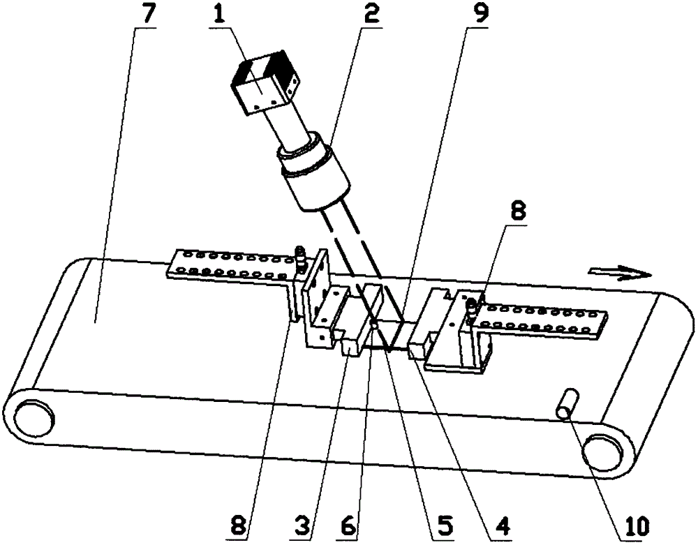
[0032] An embodiment of the present invention provides an online detection lighting device, which is composed of a front strip light source group 3 , a rear strip light source group 4 , a light source fixing device 8 , a lens 2 , a camera 1 and a photosensitive sensor 6 . The camera 1 is connected to the rear end of the lens 2 and is fixed above the conveyor belt 7 together. Lens 2 adopts a large field of view industrial lens to meet the imaging requirements of a series of medium-sized workpieces. The front strip light source group 3 and the rear strip light source group 4 are located above the conveyor belt 7 and below the camera 1 and the lens 2 . The front bar-shaped light source group 3 is the front light source, which is located at the direction where the detected workpiece 5 enters the device.

[0033] The front bar-shaped light source group 3 and the rear bar-shaped light source group 4 are fixed by the light source fixing device 8, and the light source fixing device 8...


PUM


Abstract

The invention provides an illuminating device, which can be used in a detection of a workpiece. According to the device, a method of external illumination is adopted to illuminate the workpiece, so that a step of power-on illumination for the detected workpiece on a conveyer belt is avoided, a complexity of a mechanism is reduced, and the requirement on detection at a high speed is met. According to the appropriate control on the brightness, position and direction of the external illumination, the detected workpiece is enabled to reflect, the surface and internal imaging effects are presented, and a camera is used for obtaining images. The illumination device comprises a strip light source, a light source fixing device, a camera lens and a camera. The invention also provides an imaging method, which comprises the steps of passing the detected workpiece through the conveyer belt, measuring a movement speed of the conveyer belt and obtaining the images.

Description

technical field [0001] The invention relates to an illuminating device and an imaging method for online detection. Background technique [0002] In the electronic equipment production industry, the production of parts must meet certain standards before they can be considered qualified products, such as information on size, position and contour, and whether there are foreign objects, dander, white spots, bright spots, scratches and dirt on the parts, etc. defect. Information on these dimensions, positions and profiles requires separate manual measurements using different equipment. The traditional way to detect defects is to use manual visual inspection, which has the disadvantages of low measurement efficiency, non-uniform measurement standards and low reliability. [0003] The production of electronic equipment parts has been mechanized and automated, but the quality inspection process has not been automated. This has become a major bottleneck in the manufacturing industr...

Claims


Application Information

Patent Timeline
Patent Type & Authority Applications(China)
IPC IPC(8): G01N21/89G01B11/00G01B11/24
Inventor 徐昕李明蔡雄飞杨聪
Owner TZTEK TECH
Why Eureka
Try Eureka