Movable contact spring of relay

A technology of moving reeds and relays, applied in the field of moving reeds, can solve the problems that the moving reeds cannot be easily separated and the contact resistance of the moving reeds is poor.

Active Publication Date: 2012-10-10
NINGBO TIANBO GANGLIAN ELECTRONICS
View PDF5 Cites 6 Cited by
  • Summary
  • Abstract
  • Description
  • Claims
  • Application Information

AI Technical Summary

Problems solved by technology

[0002] At present, there is a moving reed of a relay, which includes a body, and a moving contact installation part is formed by opening an L-shaped or a quarter arc-shaped cutout on the body. Since there is only one cutout, it is mainly located in the moving contact installation part. In this way, a larger force is required to push the moving reed to swing. Taking the main part of the cutout located on the left side of the moving contact installation part as an example, the moving reed is pushed by both ends, and the pushing contact parts are respectively moving The left and right ends of the reed are respectively located on the left and right sides of the movable contact installation part. Since the main part of the cutout is located on the left side of the movable contact installation part, the part of the body located on the right side of the movable contact installation part is basically If it is integrated with the moving contact installation part, the force required to push the right end must be greater than the force required to push the left end. However, the mechanism that applies the thrust will only apply one force and will not distinguish between the left and right ends. The force is based on the force required to push the right end. The problem caused when the main part of the cutout is located on the right side of the moving contact installation part is the same as the above-mentioned case on the left side. It is based on the maximum force required to push the moving reed, and because the moving and static contacts have a certain temperature after contact, in this way, in long-term work, a larger thrust will cause the contact resistance of the moving reed to be weaker. Poor, that is, a large thrust will cause the moving contact and the static contact installed on the moving contact installation part to be tightly bonded together and cannot be easily separated

Method used


Image

  • Movable contact spring of relay
  • Movable contact spring of relay
  • Movable contact spring of relay

Examples


Embodiment Construction

[0014] The present invention will be further described below in conjunction with accompanying drawing.

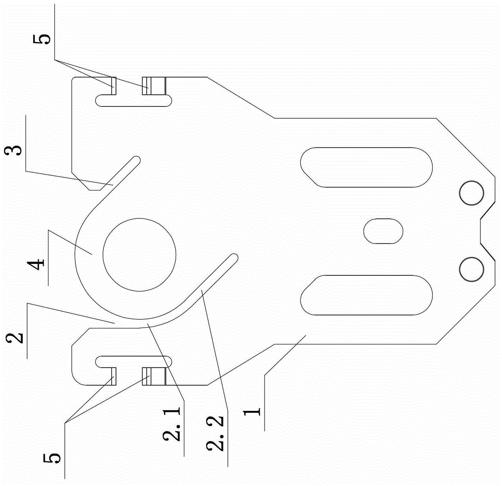
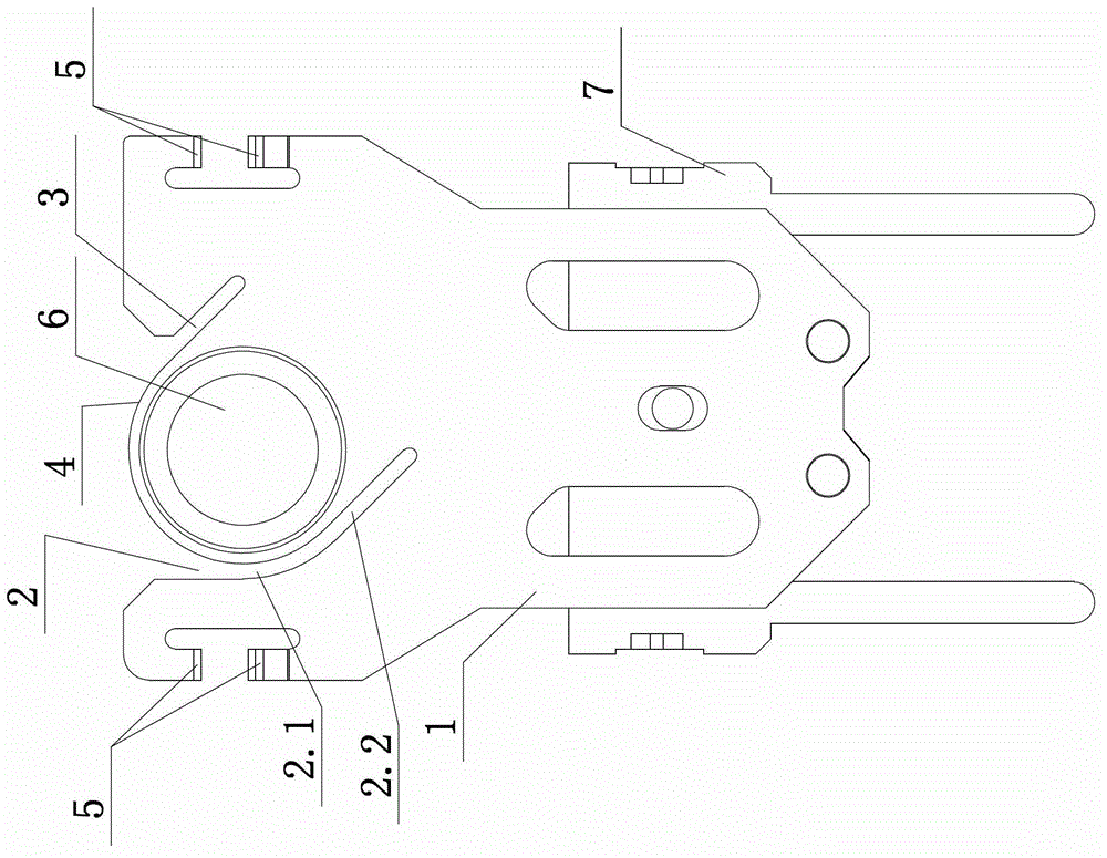
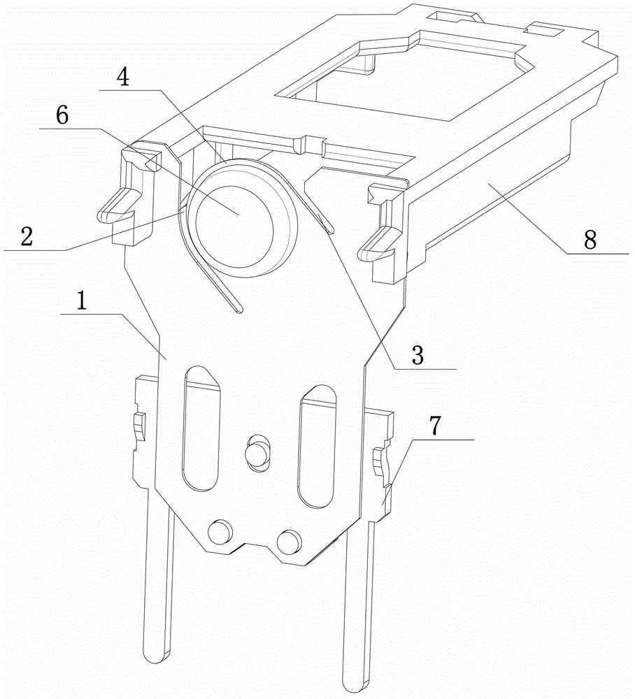
[0015] The moving reed of the relay of the present invention includes a body 1, the body 1 has a first cutout 2 and a second cutout 3, and the part of the body 1 between the first cutout 2 and the second cutout 3 is installed as a movable contact part 4.

[0016] The first incision 2 is formed by sequentially connecting the arc portion 2.1 and the straight portion 2.2; the second incision 3 is a straight incision.

[0017] The straight portion 2.2 of the first cutout 2 and the second cutout 3 are parallel to each other.

[0018] Both the straight line portion 2.2 and the second cutout 3 are oblique cutouts.

[0019] The inclination angle of the oblique cut is 45 degrees, and the inclination angle can also be 30 degrees, 40 degrees, 50 degrees, 55 degrees or the like.

[0020] In order to easily understand the moving reed of the relay of the present invention, figure 2 ...


PUM


Abstract

The invention discloses a movable contact spring of a relay, which has good anti-contact adhesion performance. The movable contact spring of the relay comprises a body (1), wherein the body (1) is provided with a first notch (2) and a second notch (3); and the part of the body (1), which is located between the first notch (2) and the second notch (3), is a movable contact mounting part (4).

Description

technical field [0001] The invention relates to the technical field of relays, in particular to a movable reed of a relay. Background technique [0002] At present, there is a moving reed of a relay, which includes a body, and a moving contact installation part is formed by opening an L-shaped or a quarter arc-shaped cutout on the body. Since there is only one cutout, it is mainly located in the moving contact installation part. In this way, a larger force is required to push the moving reed to swing. Taking the main part of the cutout located on the left side of the moving contact installation part as an example, the moving reed is pushed by both ends, and the pushing contact parts are respectively moving The left and right ends of the reed are respectively located on the left and right sides of the movable contact installation part. Since the main part of the cutout is located on the left side of the movable contact installation part, the part of the body located on the ri...

Claims


Application Information

Patent Timeline
Patent Type & Authority Applications(China)
IPC IPC(8): H01H50/64
Inventor 王铁伟王坚敏郭板宇
Owner NINGBO TIANBO GANGLIAN ELECTRONICS
Why Eureka
Try Eureka