
Ultra-wide-band dual-notch paster antenna adopting wide-attenuation-band electromagnetic band gap structure

An electromagnetic bandgap structure, patch antenna technology, applied in the direction of antenna, antenna coupling, antenna grounding device, etc., can solve the problems of improving the antenna radiation pattern, achieve light weight, small size, reduce top and back direction effect of radiation

Active Publication Date: 2015-01-07
BEIHANG UNIV
View PDF10 Cites 0 Cited by
  • Summary
  • Abstract
  • Description
  • Claims
  • Application Information

AI Technical Summary

Problems solved by technology

None of the above patents improved the radiation pattern of the antenna

Method used


Image

  • Ultra-wide-band dual-notch paster antenna adopting wide-attenuation-band electromagnetic band gap structure
  • Ultra-wide-band dual-notch paster antenna adopting wide-attenuation-band electromagnetic band gap structure
  • Ultra-wide-band dual-notch paster antenna adopting wide-attenuation-band electromagnetic band gap structure

Examples


Embodiment Construction

[0063] The present invention is described in detail below with reference to the accompanying drawings and specific embodiments, but is not intended to limit the present invention.

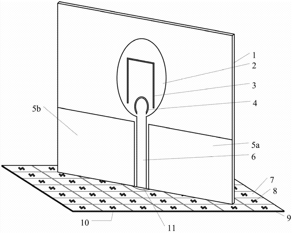
[0064] like figure 1 As shown, the ultra-wideband dual-notch patch antenna stands vertically on the first surface of the wide stopband electromagnetic bandgap structure. The broad side of the rectangular dielectric substrate 1 is parallel to the diagonal direction of the first surface of the electromagnetic band gap structure, and the center of the first surface of the electromagnetic band gap structure is located on the longitudinal center axis of the rectangular dielectric substrate 1 .

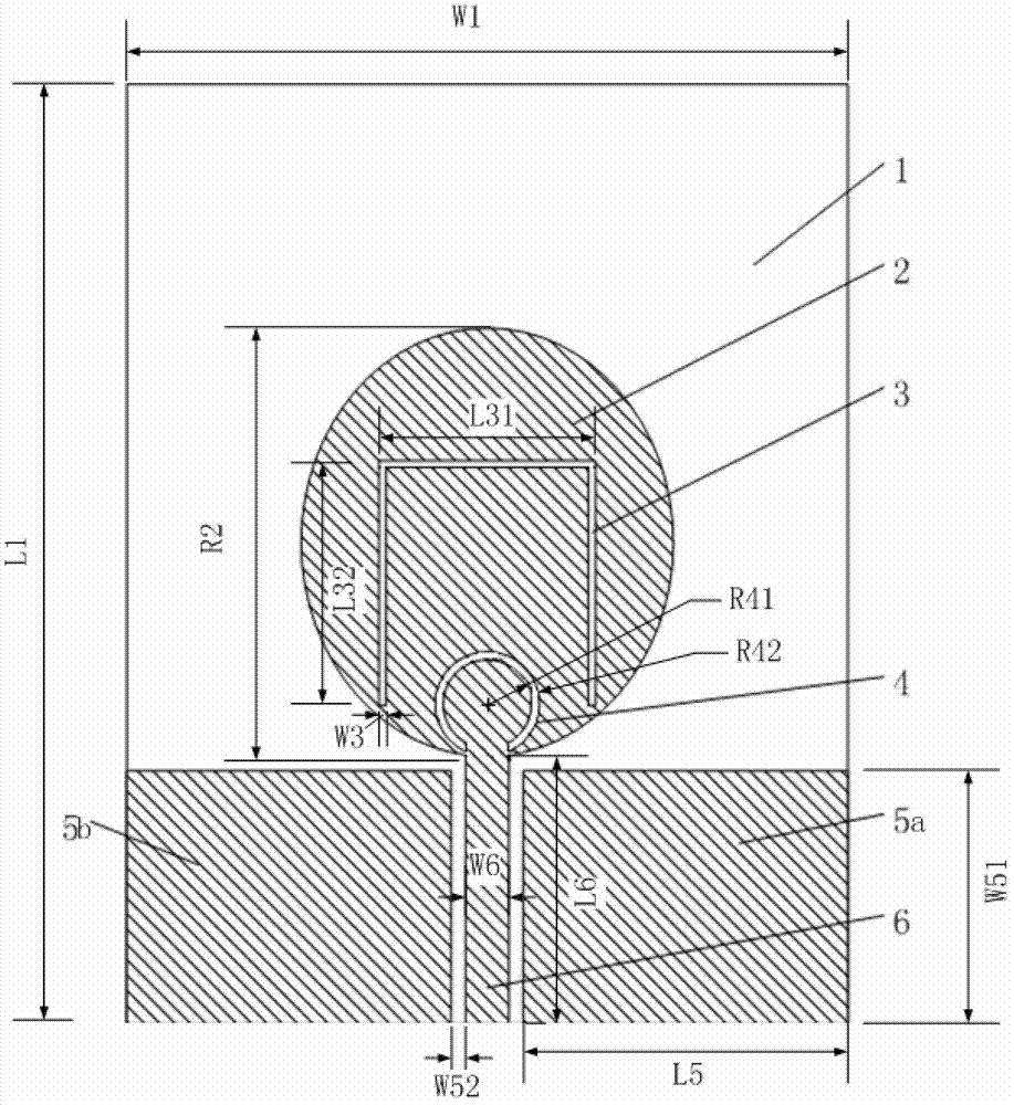
[0065] The ultra-wideband dual-notch patch antenna is made of a single-sided copper-clad printed circuit board by plate-making technology. In a specific preferred embodiment, the length L1 of the rectangular dielectric substrate 1 is 56 mm, the width W1 is 50 mm, the thickness H1 is 1.5367 mm, and the dielectri...


PUM


Abstract

The invention relates to an ultra-wide-band dual-notch paster antenna adopting a wide-attenuation-band electromagnetic band gap structure. The antenna comprises a wide-attenuation-band electromagnetic band gap structure and an ultra-wide-band dual-notch paster antenna, wherein the wide-attenuation-band electromagnetic band gap structure is formed in the way that multiple hole-penetrating electromagnetic band gap units are periodically arranged, and comprises a square metal paster, metalized penetrating holes, a central round through hole, a square medium substrate and a metal floor; the ultra-wide-band dual-notch paster antenna comprises an oval metal paster provided with a combined slot liner of a reversed-U-shaped slot liner and an opened ring-shaped slot liner, a microstrip line, an antenna grounding part, a rectangular medium substrate and a coaxial line; the oval metal paster provided with the combined slot liner of the reversed-U-shaped slot liner and the opened ring-shaped slot liner, the microstrip line and the antenna grounding part are located on the same plane and manufactured on the rectangular substrate to achieve the ultra-wide-band dual-notch performance. According to the invention, the forward and backward radiation of the antenna is reduced by the performance of the wide attenuation band of the porous electromagnetic band gap structure, and the omnidirectional radiation performance of the antenna is improved.

Description

technical field [0001] The invention relates to an antenna in the field of microwave communication, in particular to an ultra-wideband double-notch patch antenna adopting a wide stopband electromagnetic bandgap structure. Background technique [0002] At present, ultra-wideband short-distance wireless communication has become a major research hotspot due to its advantages of low cost, high transmission data rate, and low transmission power. However, since there are other frequency bands such as 2.4GHz (2.405-2.485GHz) industrial, scientific and medical frequency bands and wireless local area network (IEEE802. Potential interference between systems usually requires the introduction of a band-stop filter in the ultra-wideband system to filter out narrow-band interference, but this will inevitably increase the complexity and cost of the system. A simple and effective method is to enable the broadband antenna to simultaneously generate stop bands in two frequency bands (2.405-2...

Claims


Application Information

Patent Timeline
Patent Type & Authority Patents(China)
IPC IPC(8): H01Q1/52H01Q1/38H01Q1/48H01Q1/50H01Q19/00
Inventor 张岩马妍石庆琳林珊珊吕善伟
Owner BEIHANG UNIV
Learn More