
Device and method for carrying out real-time splicing on surveillance videos based on FPGA (field programmable gata array)

A technology of monitoring video and splicing device, which is applied in the direction of TV, color TV, closed-circuit TV system, etc., can solve the problems of visual blind spot, picture distortion, inability to be intuitive, etc., and achieve the effect of real-time monitoring with wide and wide angle.

Inactive Publication Date: 2012-10-10
HEILONGJIANG UNIV
View PDF4 Cites 20 Cited by
  • Summary
  • Abstract
  • Description
  • Claims
  • Application Information

AI Technical Summary

Problems solved by technology

However, wide-angle lenses and fisheye lenses will cause image distortion and distortion, especially for fisheye lenses. It is necessary to effectively expand and process the output video image to obtain a tiled image that the human eye is accustomed to.
The price of this type of product is high, and the image distortion is relatively large. Although the image is effectively processed, the image distortion is still very obvious.
Although the dome camera can realize scene video monitoring within a wide viewing angle range, this method cannot monitor all objects in the monitoring area at the same time, and there are visual blind spots
Due to the existence of rotating devices, easy to wear and affect the service life
A panoramic camera with multi-lens splicing, which uses multiple ordinary cameras distributed at different angles to collect video at the same time, and obtain a full range of video signals in the monitoring area. The output signals of each camera in most products are independent of each other, and users can only directly observe a certain area. Images from different angles cannot visualize the situation in the entire monitoring area, and the simultaneous transmission of multiple videos also increases the complexity and cost of the project

Method used


Image

  • Device and method for carrying out real-time splicing on surveillance videos based on FPGA (field programmable gata array)
  • Device and method for carrying out real-time splicing on surveillance videos based on FPGA (field programmable gata array)
  • Device and method for carrying out real-time splicing on surveillance videos based on FPGA (field programmable gata array)

Examples


specific Embodiment approach 1

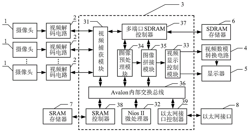
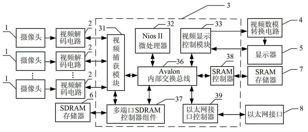
[0024] The specific embodiment one, monitoring video real-time splicing device based on FPGA, monitoring video real-time splicing device, it comprises N cameras 1, and it also comprises N video decoding circuits 2, FPGA control circuit 3, video digital-to-analog conversion circuit 4 and display 5, FPGA control circuit 3 comprises video capture module 31, Nios II microprocessor 32, video display control module 33, image preprocessing module 34, image splicing module 35 and Avalon internal exchange bus 36; Video capture module 31, Nios II microprocessor Processor 32, image preprocessing module 34, image splicing module 35 are all mounted on the Avalon internal switching bus 36; the camera signal output ends of N cameras 1 are connected with the camera signal input ends of N video decoding circuits 2 respectively, N The video signal output ends of two video decoding circuits 2 are respectively connected with the N road video signal input ends of the video capture module 31; the im...

specific Embodiment approach 2

[0031] Embodiment two, the difference between this embodiment and the monitoring video real-time splicing device based on FPGA described in embodiment one is that it also includes SDRAM memory 6, and FPGA control circuit 3 also includes multi-port SDRAM controller 37, so The video signal input or output end of the multiport SDRAM controller 37 is connected with the video signal output or input end of the video capture module 31; the image preprocessing signal input or output end of the multiport SDRAM controller 37 is connected with the image preprocessing module 34 image preprocessing signal output or input end connection; the image mosaic signal input or output end of described multi-port SDRAM controller 37 is connected with the image mosaic signal output or input end of image mosaic module 35; described multi-port SDRAM controller The SDRAM control signal output or input end of 37 is connected with the SDRAM control signal input or output end of SDRAM memory 6 .

specific Embodiment approach 3

[0032] Specific embodiment three, the difference between this specific embodiment and the monitoring video real-time splicing device based on FPGA described in specific embodiment one or two is that it also includes SRAM memory 7, and FPGA control circuit 3 also includes SRAM controller 38, so The SRAM controller 38 is connected to the Avalon internal switching bus 36; the SRAM control signal input or output end of the SRAM controller 38 is connected to the SRAM control signal output or input end of the SRAM memory 7.


PUM


Abstract

The invention discloses a device and method for carrying out real-time splicing on surveillance videos based on FPGA (field programmable gata array), which relate to a surveillance video splicing device and a surveillance video splicing method, and aim to achieve an effect of carrying out real-time seamless splicing on video signals output by multiple channels of cameras. Under the control of a video capturing circuit, a video decoding circuit converts multiple channels of video signals from a plurality of cameras into digital signals, then the digital signals are corrected by an image preprocessing module, and after the digital signals enter into an image splicing module to implement the seamless splicing of each frame of images, a video display control module controls a video digital-to-analog conversion circuit to output the video subjected to splicing to a display in real time. According to the invention, the video signals output by the multiple channels of cameras can be subjected to real-time seamless splicing, and the video signals with partial overlapped scenes, output by the multiple channels of cameras, can be subjected to space matching alignment, then the video signals are subjected to seamless splicing so as to form a channel of wide-scene video, and low-distortion video signals subjected to splicing are directly output on the display. The device and method disclosed by the invention are applicable to the real-time splicing of the surveillance videos.

Description

technical field [0001] The invention relates to a monitoring video splicing device and a splicing method. Background technique [0002] With the rapid development of video surveillance, market applications continue to expand in depth and breadth, which promotes the rapid progress of video surveillance technology. In order to meet the market demand of being able to see a wider range of surveillance scenes at the same time, wide-angle and panoramic video surveillance technologies have been developed rapidly. [0003] The main methods for realizing wide-angle and panoramic video surveillance in the domestic video surveillance industry are: (1) using wide-angle lenses and fisheye lenses to expand the field of view of video surveillance; Viewing angle and even 360-degree monitoring; (3) Multi-camera stitching is used to realize 360-degree monitoring. At present, the domestic monitoring product market mainly adopts wide-angle lens or fisheye lens method. When the fisheye lens i...

Claims


Application Information

Patent Timeline
Patent Type & Authority Applications(China)
IPC IPC(8): H04N7/18H04N5/265
Inventor 杜西亮张强
Owner HEILONGJIANG UNIV
Learn More