Exhaust device with deflection plate

A technology of exhaust device and deflection plate, which can be applied to home appliances, cleaning methods and appliances, and dust removal, etc. It can solve the problems of inability to completely block harmful gas leakage, unstable vortex, etc., to reduce large backflow, reduce The effect of leakage

Active Publication Date: 2012-10-17
黄荣芳
View PDF9 Cites 9 Cited by
  • Summary
  • Abstract
  • Description
  • Claims
  • Application Information

AI Technical Summary

Problems solved by technology

However, the left and right side panels (e, e1) are all closed facades, when the air enters from the gap between the two ends of the air blowing end (b, b1) and the left and right side panels (e, e1) respectively Finally, accord

Method used


Image

  • Exhaust device with deflection plate
  • Exhaust device with deflection plate
  • Exhaust device with deflection plate

Examples


Embodiment Construction

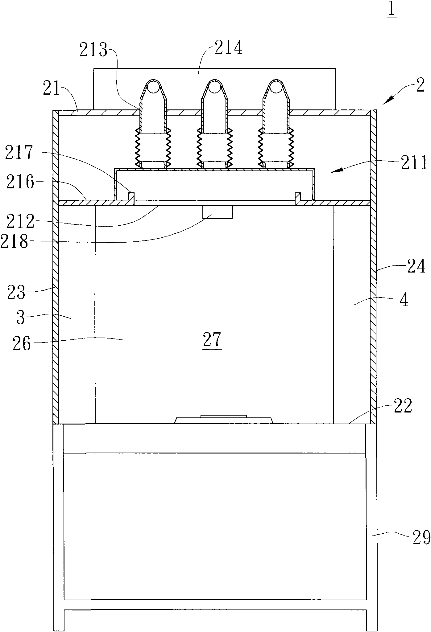
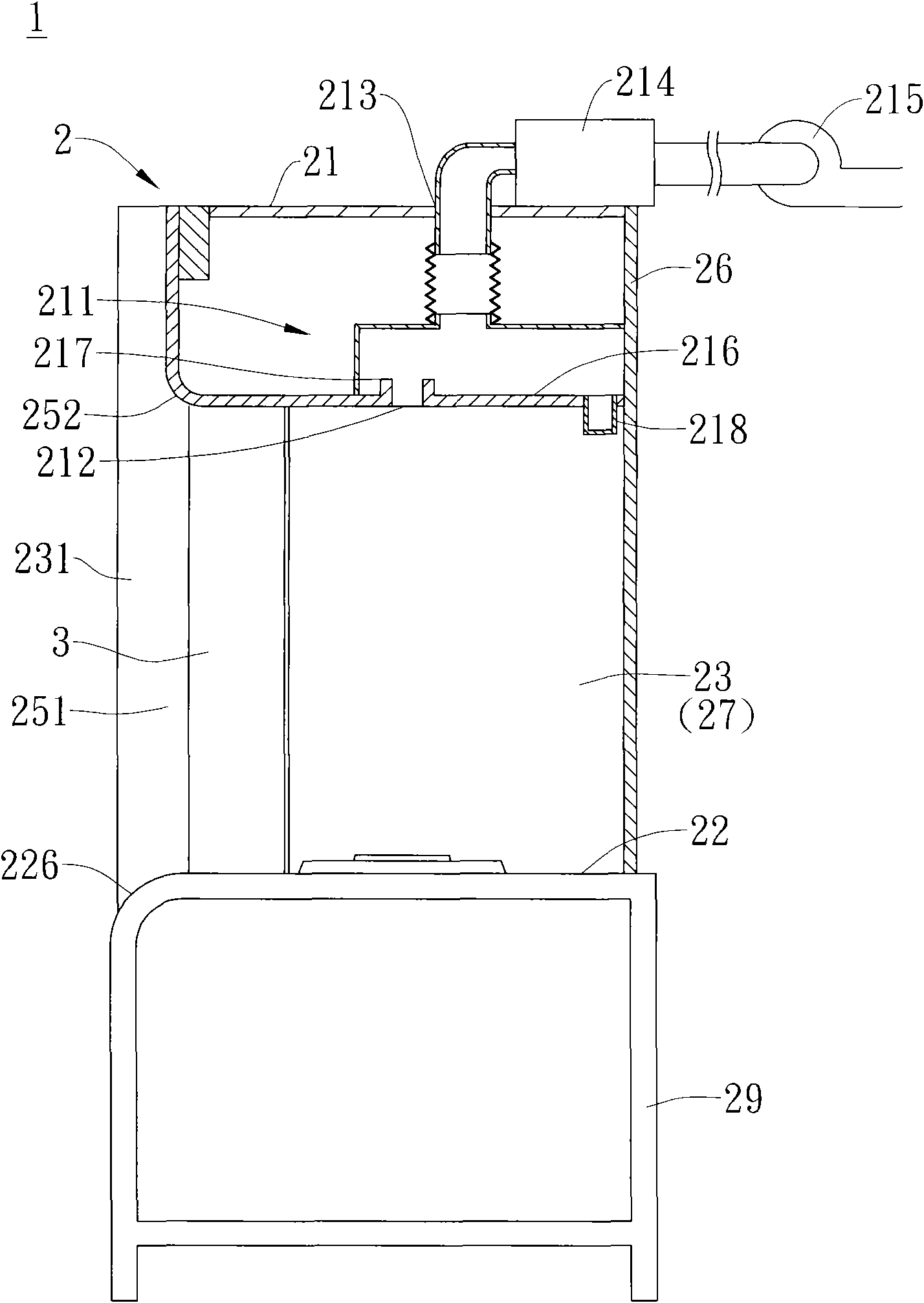
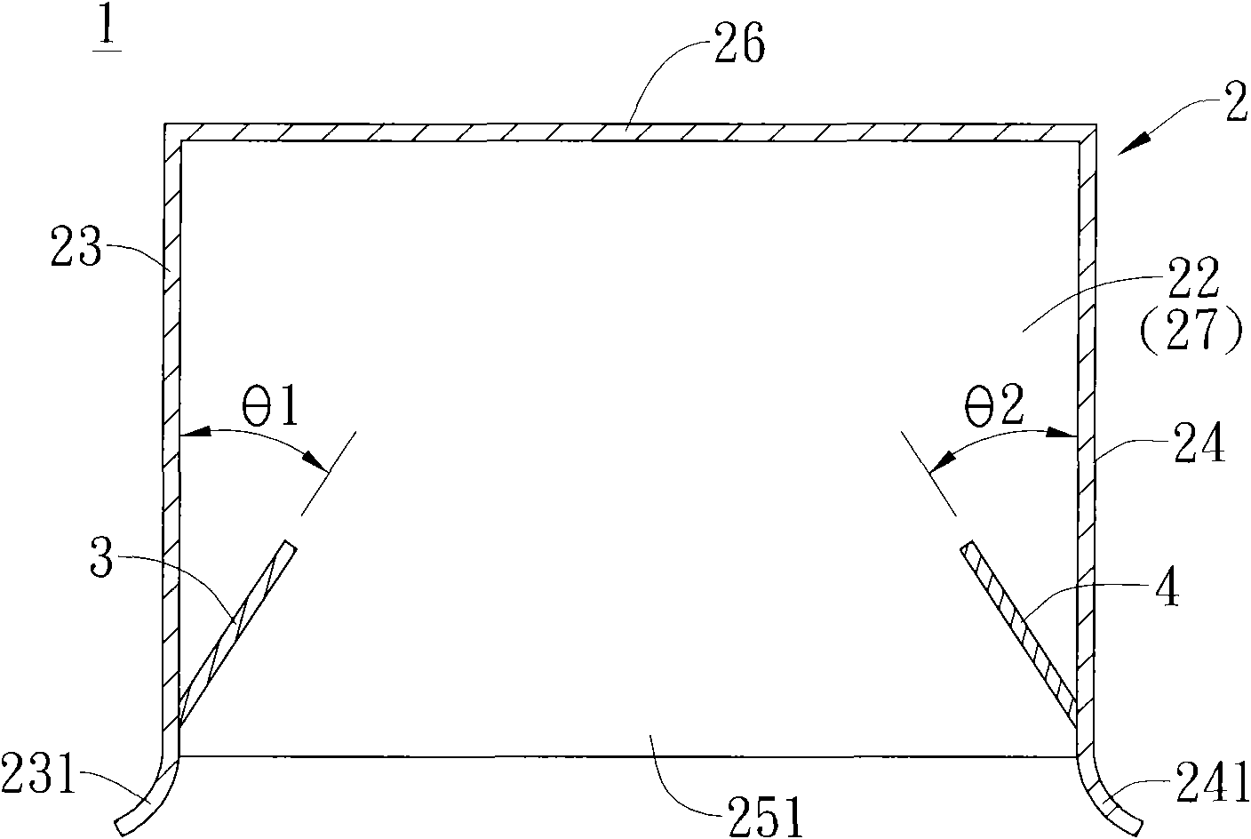
[0051] Such as Figure 1-3 As shown, it is the first embodiment of the exhaust device 1 with deflecting plates of the present invention, which includes an operation cabinet 2 , a left deflecting plate 3 and a right deflecting plate 4 .

[0052] The operating cabinet 2 is roughly in the shape of a cuboid, and a locker 29 with legs is provided below it to support the operating cabinet 2 upwards and store objects. The operating cabinet 2 includes a suction hood 21, a bottom plate 22, and a left side plate 23. A right side panel 24 and a rear panel 26. After the panels are combined, an accommodating space 27 is formed inside the operation cabinet 2, and an opening 251 is formed under the front end of the suction hood 21. And the bottom of the front end of the suction hood 21 is provided with an arc-shaped first guide portion 252, and the top of the front end of the base plate 22 is provided with an arc-shaped second guide portion 226, and the left side plate 23 in the operation ca...


PUM


Abstract

The invention discloses an exhaust device with a deflection plate, which comprises an operation cabinet, wherein an accommodating space is formed in the operation cabinet, an opening is formed in front of the operation cabinet, the bottom of a suction hood on the top end of the operation cabinet is provided with a narrow and long extraction opening which faces downwards and is parallel with a rear plate, a left deflection plate is vertically fixed in the accommodating space in a manner of being inclined relative to a left side plate, a right deflection plate and the left deflection plate are symmetrical, and the right deflection plate is vertically fixed in the accommodating space in a manner of being inclined relative to a right side plate. Therefore, when the narrow and long sucks air upwards, by means of the guidance of the left deflection plate and the right deflection plate, air enters in the operation cabinet, and polluted materials are prevented from leaking outwards from the opening in front of the operation cabinet.

Description

technical field [0001] The invention relates to an exhaust device with a deflecting plate, especially a deflecting plate that can guide the airflow in the operation cabinet to prevent the leakage of pollutants, and is suitable for exhaust cabinets in factories and laboratories and commercial Exhaust unit with deflector for kitchen hoods. Background technique [0002] In the prior art, the air extraction method of the traditional exhaust cabinet is to set up an opening shutter at the upper end of the gas cabinet, and erect a deflector with a specially designed opening at the rear of the cabinet body, and discharge the air in the cabinet through the exhaust device and the duct. Harmful gas is extracted through the opening of the upper shutter and the opening of the deflector at the rear of the cabinet. When using the exhaust cabinet, the suction device must be running to perform the pumping action. At this time, the door of the gas cabinet cannot be completely closed or an ai...

Claims


Application Information

Patent Timeline
IPC IPC(8): B08B15/04F24C15/20
Inventor 黄荣芳
Owner 黄荣芳
Why Eureka
Try Eureka