Lifting mechanism of parallel connecting lever type large-tonnage forging manipulator

A technology for forging manipulators and parallel connecting rods, used in forging/pressing/hammering machinery, manufacturing tools, forging/pressing/hammer devices, etc. Reduce synchronization efficiency and other problems to achieve the effect of reducing force, ensuring parallelism, and improving overall bearing capacity

Inactive Publication Date: 2012-10-17
YANSHAN UNIV
View PDF8 Cites 43 Cited by
  • Summary
  • Abstract
  • Description
  • Claims
  • Application Information

AI Technical Summary

Problems solved by technology

Among them, the parallel link type forging manipulator has high motion decoupling and is easy to control. If the synchronization rod of the parallel link type forging manipulator is placed at the top, it can reduce the force on the hinge joint of the frame, but most of the synchronous The rod top parallel link type forging manipulator only contains a single pitching hydraulic cylinder, such as Chinese patents 201010543863.5, 201010133714.1, etc. The manipulator clamping capacity of this structure is not very large
In Chinese patent 201010193620.3, although there are two pitching hydraulic cylinders, the pitching hydraulic cylinder is placed in the middle of the synchronization rod, which not only reduces its synchronization efficiency, but also tends to reduce the parallelism of lifting and lowering.

Method used


Image

  • Lifting mechanism of parallel connecting lever type large-tonnage forging manipulator

Examples


Embodiment Construction

[0014] The embodiments of the present invention will be described in detail below with reference to the drawings: this embodiment is implemented on the premise of the technical solution of the present invention, and detailed implementation modes and specific operation procedures are given, but the protection scope of the present invention is not limited to the following Mentioned examples.

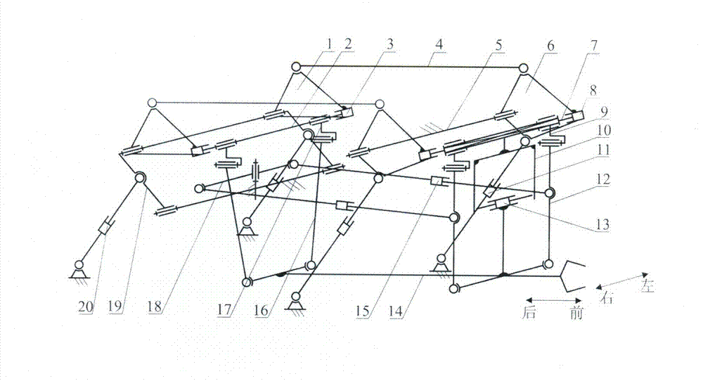
[0015] in figure 1 The three-dimensional schematic diagram of the lifting mechanism of a parallel link type large tonnage forging manipulator is shown. The swing device is installed on the upper part of the lifting device, the clamp rod is installed on the bottom of the lifting device, and the front ends of the front and rear buffer devices are connected to the front of the lifting device. The middle part of the suspension rod and the rear end are connected with the frame, and the left and right buffer devices are installed between the two front suspension rods.

[0016] The lifting device inc...


PUM


Abstract

A lifting mechanism of a parallel connecting lever type large-tonnage forging manipulator is mainly characterized in that the front part and the rear part of a nipping lever are respectively connected with the lower ends of a front suspension lever and a rear suspension lever, the upper ends of the front and rear suspension levers are respectively connected on front and rear sliding levers by connecting pieces, left and right linear drivers are arranged at two ends of the front and rear sliding levers and are connected with front and rear lifting arms, and the other end of the lifting arm is connected with a rack. The lower arms of the two front lifting arms are connected with the upper ends of the two linear lifting drivers, the upper arms of the front lifting arms are connected with the front end of a horizontal synchronous lever, the rear end of the synchronous lever is connected with the upper arms of the rear lifting arms, the other ends of the two rear lifting arms are connected with one end of a pitching arm, and the other end of the pitching arm is connected with the rack. The middle parts of the two pitching arms are also connected with the upper ends of linear pitching drivers. The lifting mechanism reduces the stress at the connection part of the rack hinges, greatly improves the whole bearing capacity and transmission efficiency of the manipulator, is applicable to forging operation of large-tonnage forged pieces, and can also ensure the lifting parallelism of the nipping lever.

Description

Technical field [0001] The invention relates to a forging manipulator of a forging hydraulic unit, particularly its lifting mechanism. Background technique [0002] As an important auxiliary equipment of forging hydraulic unit, forging manipulator plays a vital role in improving the forging quality of forgings and the production efficiency of unit equipment. Generally speaking, the forging manipulator needs to realize seven forging operation functions including jaw clamping, pliers rod rotation, pliers rod lifting, pliers rod pitching, pliers rod lateral movement, pliers rod swing, and cart walking. Among them, the three actions of jaw clamping, clamp rod rotation, and cart walking are structurally independent of each other. They are independently driven by motors or hydraulic cylinders. The clamp realizes the clamping and rotating functions of the workpiece, and the cart assumes the walking function. The action is realized by the lifting mechanism. At present, there are two ty...

Claims


Application Information

Patent Timeline
Patent Type & Authority Applications(China)
IPC IPC(8): B21J13/10
Inventor 赵永生许允斗
Owner YANSHAN UNIV
Why Eureka
Try Eureka