
Annular part fixture

A technology of ring parts and fixtures, which is applied in the direction of manufacturing tools, forging/pressing/hammer devices, forging/pressing/hammering machinery, etc., which can solve the problems of poor firmness of clamping workpieces, low strength of claws, and easy falling off of workpieces, etc. , to achieve the effects of small clamping force, high clamping rigidity and reduced residual stress

Inactive Publication Date: 2014-09-17
JIANGSU UNIV
View PDF4 Cites 4 Cited by
  • Summary
  • Abstract
  • Description
  • Claims
  • Application Information

AI Technical Summary

Problems solved by technology

At present, arc-type floating fixtures and mandrel-type floating fixtures are widely used, but some problems have also been found in use. The arc-type floating fixtures hold the workpiece firmly but have poor floating performance, while the mandrel-type floating fixtures have good floating performance. But the strength of the claw is not high, it is easy to break, and the firmness of clamping the workpiece is poor, and the workpiece is easy to fall off

Method used


Image

  • Annular part fixture
  • Annular part fixture
  • Annular part fixture

Examples


Embodiment Construction

[0017] In order to make the object, technical solution and advantages of the present invention clearer, the present invention will be further described in detail in conjunction with the accompanying drawings.

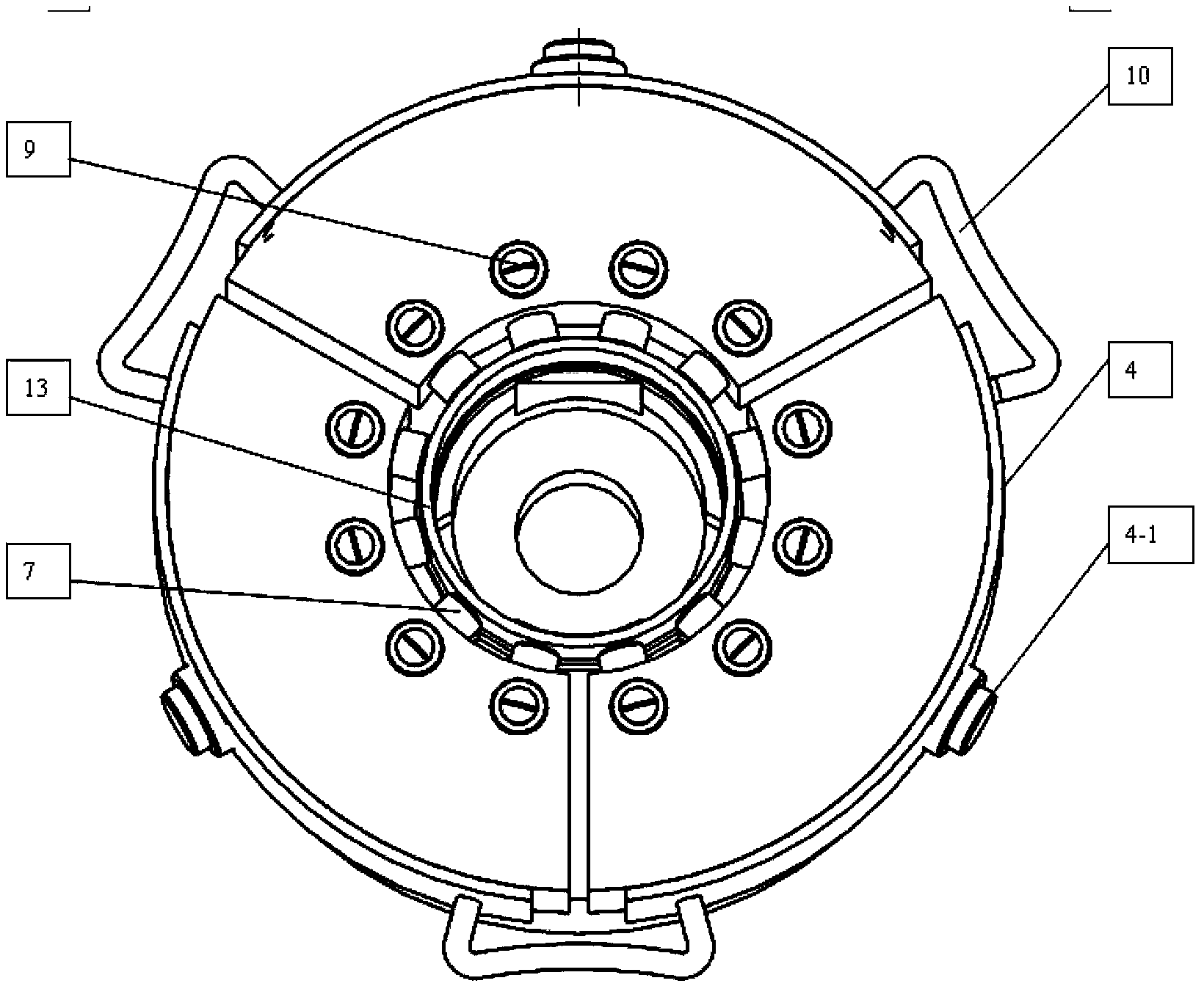
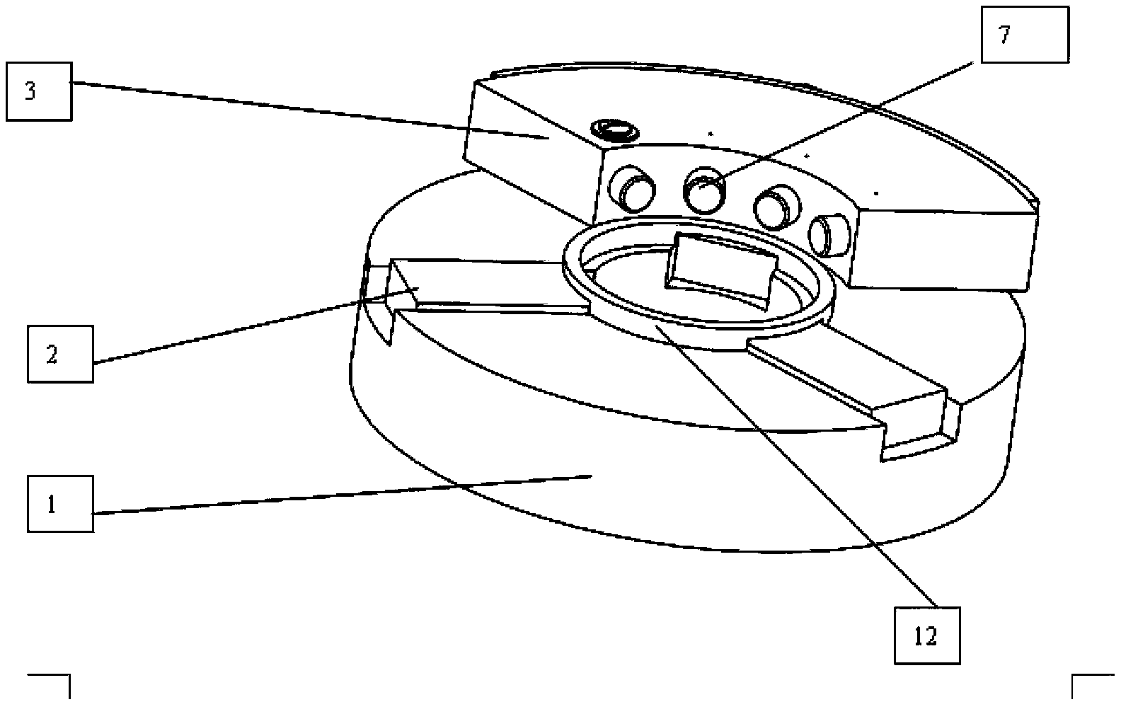
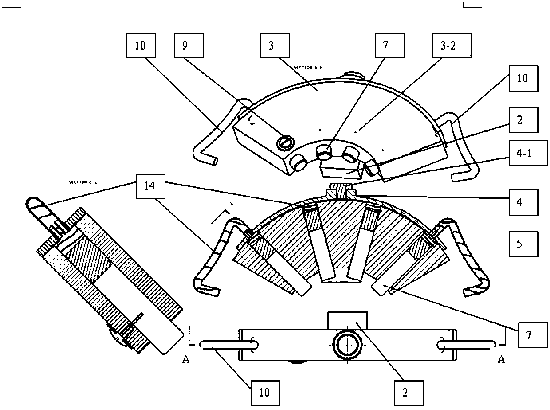
[0018] Such as figure 1 , figure 2 The shown annular part fixture of the present invention includes a three-jaw wedge power chuck seat 1, a base jaw 2, a jaw hydraulic seat 3, an arc-shaped sealing seat 4, a jaw 7, a hydraulic hose 10, and an end positioning ring 12, Ring workpiece 13. On the jaw hydraulic seat 3, several jaw base holes 3-1 are evenly distributed radially with the center of the three-jaw wedge power chuck seat 1 as the axis. Jaw base hole 3-1 is integrally slidably matched with jaw piston 5, the front end of jaw piston 5 is in contact with jaw 7, the rear end of jaw piston 5 is in contact with hydraulic oil 14, and jaw piston 5 is in jaw base hole 3-1 Under the action of internal hydraulic oil, the jaws 7 are pushed to move radially along the center...


PUM


Abstract

The invention relates to an annular part fixture, which comprises a three-jaw wedge power chuck seat and a plurality of base jaws arranged on the three-jaw wedge power chuck seat. The annular part fixture is characterized in that the base jaws are fixedly connected with a clamping jaw hydraulic seat, a plurality of clamping jaw base holes are evenly arranged on the clamping jaw hydraulic seat with the circle center of the three-jaw wedge power chuck seat serving as the axle center, clamping jaw pistons and clamping jaws are successively arranged in the clamping jaw base holes, and the clamping jaw pistons push the clamping jaw to perform radial motion along the circle center of the three-jaw wedge power chuck seat under the action of internal hydraulic oil of the clamping jaw base holes. The annular part fixture can clamp irregularly-shaped annular forge piece blanks evenly and has the advantages that clamping force is more balanced, residual stress is remarkably reduced, required clamping force is smaller and clamping rigidity is larger, and clamping is firm.

Description

technical field [0001] The invention relates to a fixture for holding workpieces, in particular to a fixture for ring parts. Background technique [0002] Thin-walled ring parts are easily deformed during clamping and processing, and it is difficult to control processing accuracy and improve processing efficiency. Machining distortion and machining efficiency have become bottlenecks in the machining of thin-walled ring parts. The fixture is a thin-walled link in the processing of thin-walled ring parts. Although the old-fashioned soft jaws and spring fixtures have been replaced by more advanced floating fixtures, the clamping force of the floating fixture is relatively balanced. At present, arc-type floating fixtures and mandrel-type floating fixtures are widely used, but some problems have also been found in use. The arc-type floating fixtures hold the workpiece firmly but have poor floating performance, while the mandrel-type floating fixtures have good floating performan...

Claims


Application Information

Patent Timeline
Patent Type & Authority Patents(China)
IPC IPC(8): B21J13/10
Inventor 赵东宏卢章平王淑梅杨华春
Owner JIANGSU UNIV
Learn More