
Method for fastening member with high strength and low riveting force and 10.9-level short-tail pulling rivet

A high-strength, pull-rivet technology, applied in rivets and other directions, can solve the problems of complex riveting and riveters, riveting impact force and noise, and achieve stable processing, improved fastening performance, and good anti-loosening performance.

Active Publication Date: 2014-11-05
MEISHAN CRRC FASTENING SYST CO LTD
View PDF8 Cites 0 Cited by
  • Summary
  • Abstract
  • Description
  • Claims
  • Application Information

AI Technical Summary

Problems solved by technology

[0004] The fastening method for components with high strength and low riveting force and the 10.9-grade short tail rivet proposed by the present invention are aimed at solving the problem of the large impact force and noise caused by the riveting of the existing "ordinary rivets".
"Reusable Rivet" riveting and riveter are more complicated

Method used


Image

  • Method for fastening member with high strength and low riveting force and 10.9-level short-tail pulling rivet
  • Method for fastening member with high strength and low riveting force and 10.9-level short-tail pulling rivet
  • Method for fastening member with high strength and low riveting force and 10.9-level short-tail pulling rivet

Examples


Embodiment Construction

[0021] The method for fastening components with high strength and low riveting force in this embodiment consists of the following steps:

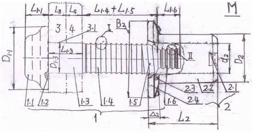
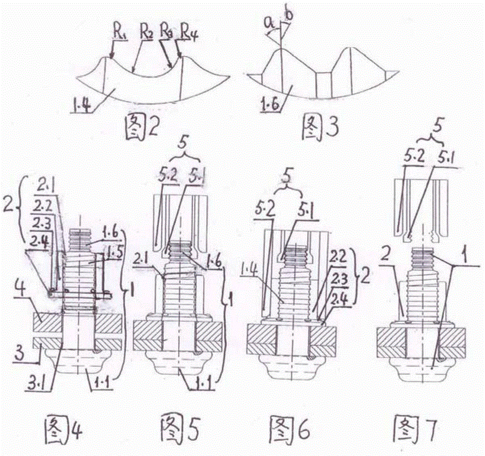
[0022] Step 1: see figure 1 , make the following ⒑9 short-tail rivets M: ① Short-tail rivets M are composed of rivets 1 and collars 2. ② Rivet 1 is composed of nail head ⒈1 connected in sequence from the front end to the rear end, unloading groove ⒈2 opened at the root of the rear end of the nail head ⒈2, polished rod ⒈3, locking ring groove section ⒈4 for extrusion fit with the collar The threaded section ⒈5 which is clamped by the locking teeth ⒉1 and the thin and short ring groove section 16 at the tail which is used for clamping the inner sleeve jaw of the low riveting force hydraulic riveter 5. ③ see figure 2 , Locking ring groove section ⒈4 The curved surface radii from front to back in each ring groove are R1, R2, R3, R4, wherein R1>R4, R2>R3. ④Short ring groove section ⒈6 The angle between the front slope and the radial section ...


PUM


Abstract

The invention discloses a method for fastening a member with high strength and low riveting force and a 10.9-level short-tail pulling rivet. The method comprises the following steps that: 1) the rivet consists of a rivet head, an unloading groove, a polished rod, a locking ring groove section, a threaded section and a tail thin short ring groove section; the radius of the inner curved surface of a locking groove is reduced from front to back; the angle of the inner inclined plane of the tail is reduced from front to back; a lantern ring is provided with a convex point, and a latch is arranged in an inner hole; 2) the rivet penetrates, the latch is screwed into the threaded section, and the lantern ring is hooked with the rivet; 3) the rivet extends into a riveting device, and a clamping jaw clamps the tail; 4) the riveting device is started, the lantern ring is extruded to deform to lock a ring groove, and the lantern ring moves forwards to break the convex point; and 5) the riveting device retreats, and fastening is finished. The unloading groove can eliminate stress concentration in riveting and use. The locking groove promotes metal flowing of the lantern ring during riveting and blocks metal flowing of the lantern ring in vibration or separation after riveting, so that fastening property and loosening resistance are improved. Due to the tail groove shape, the clamping jaw is engaged with the tail without releasing, and riveting with low riveting force is promoted. Due to the latch, the lantern ring is convenient to hook, install and operate. The rivet is applied to railway vehicles and heavy trucks with high requirements for fastening property and reliability.

Description

[0001] (1) Technical field: the fastening method of high-strength, low-riveting force components and the 10.9-grade short-tail pull rivets of the present invention relate to a fastening technology of high-strength, low-riveting force components. It is mainly used for component connections on railway vehicles and heavy trucks that require higher performance and reliability of the fastening system. It belongs to riveting (B21J) and fasteners (F16B) of metal machining. (2) Background technology: [0002] There are currently disclosed cold-drawn rivets and connection methods for the connection of upper components of railway vehicles. The pull rivets are all composed of rivets and collars. The difference is that due to different required functions, the shape of the designed rivets and the connection structure between them change. And the corresponding riveting method is different from the riveter structure. There are following several kinds that are close to the present invention:...

Claims


Application Information

Patent Timeline
Patent Type & Authority Patents(China)
IPC IPC(8): B21J15/10F16B19/12
Inventor 李新荣潘树平伏凯胡方年刘宇刘洋代广成贾云龙张荣
Owner MEISHAN CRRC FASTENING SYST CO LTD
Learn More