

Processing method for holes in multi-lug-plate parts with dense spaces
A processing method and lug technology, applied in the field of mechanical processing, can solve the problems of occupying the processing space of lugs, affecting the coaxiality accuracy, and scratches on the surface of parts, so as to improve quality, improve production efficiency, and reduce manufacturing costs. Effect
- Summary
- Abstract
- Description
- Claims
- Application Information
AI Technical Summary
Problems solved by technology
Method used
Image

Examples
Embodiment Construction
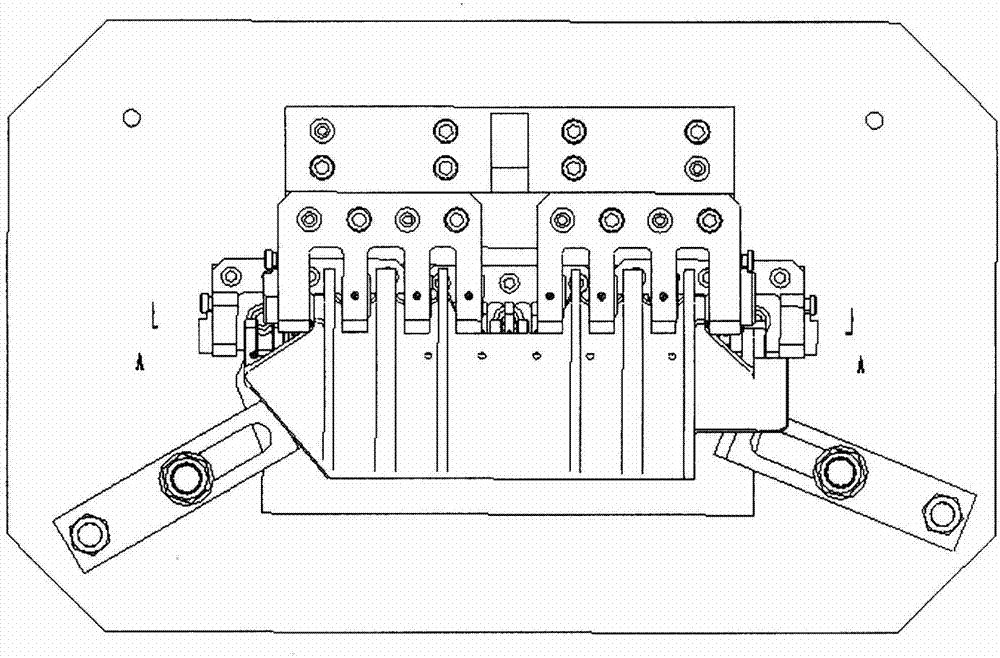
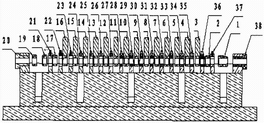
[0024] like figure 1 and figure 2 As shown in the figure, the processing method of the holes in the densely spaced multi-tab parts includes the following steps:
[0025] 1) Install the drilling template reaming guide sleeves 21 to 37 on the drilling template;
[0026] 2) Fix the part on the drill die;
[0027] 3) Install the drill template front guide sleeve 20a and the drill template rear guide sleeve 38a on the drill template, at this time, the drill template front guide sleeve 20a and the drill template rear guide sleeve 38a respectively play a guiding role during drilling;
[0028] 4) Drill holes and leave machining allowance;
[0029] 5) Reaming;
[0030] 6) Complete the machining of the holes in the multi-tab parts.
[0031] In the method for processing holes in the densely spaced multi-tab type parts, the drilling comprises the following steps:
[0032] 1) Drilling for the first time: According to the front guide sleeve 20a of the drill template and the rear guid...
PUM
 Abstract
Description
Claims
Application Information