Special double-spacing side hung mechanical protection device for injection machine

A technology of mechanical protection and double limit is applied in the field of double limit side suspension type mechanical protection device for injection molding machines, which can solve the problems of complex stress on the safety rod, affecting the working life of the structure, and short life of the mechanism, etc. The effect of mechanism maintenance cost, improving the reliability level of the whole machine, and prolonging the service life

Inactive Publication Date: 2012-10-17
浙江博创机械有限公司
View PDF4 Cites 0 Cited by
  • Summary
  • Abstract
  • Description
  • Claims
  • Application Information

AI Technical Summary

Problems solved by technology

[0003] The above-mentioned first structure has the following problems: 1) Since the direction of movement of the gate and the direction of the force of the gate are at a spatial angle, the gate must bear lateral pulling force during the working process, and the service life of the mechanism is short; 2) In order to ensure that the machine allows The mechanism is effective within the mold thickness range, and an auxiliary coordination device needs to be installed between the machine door and the tail plate that is adjusted frequently as required, and the structure is complex
[0004] The above-mentioned second structure has the following problems: 1) The safety shaft and the second plate hinge are supported by independent supports. Due to the action of gravity, there is continuous sliding friction between the safety shaft and the independent supports. Wear-resistant devices or frequent replacement of wear-resistant parts
2) During the working period of the mechanism, since the movement direction of the safety rod is along the safety rod, and the stop force exerted by the gate on the safety rod forms a certain angle with the safety rod, and presses the safety rod to the independent support, the force situation of the safety rod is complicated. Seriously affect the working life of the structure

Method used


Image

  • Special double-spacing side hung mechanical protection device for injection machine

Examples


Embodiment Construction

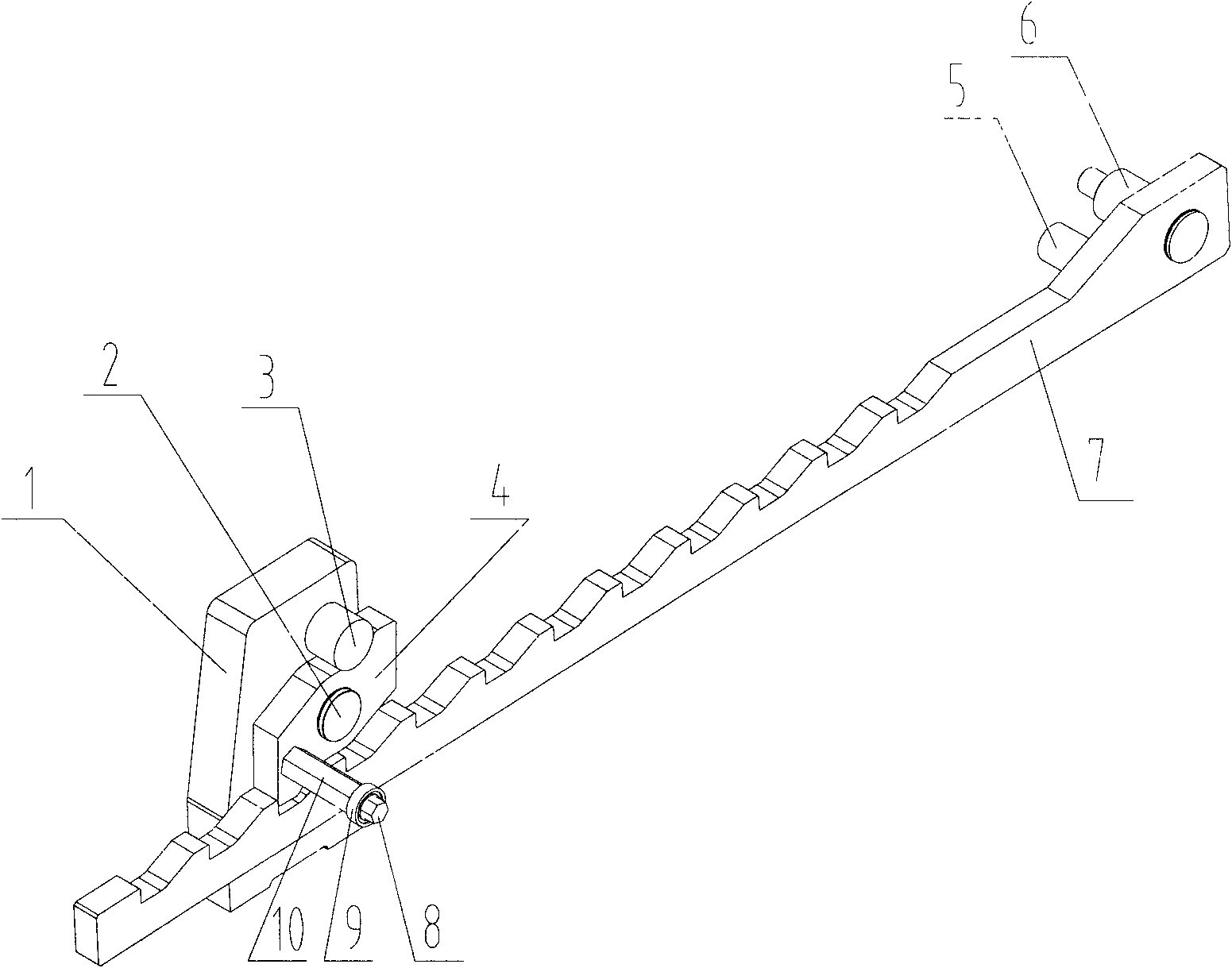
[0013] 1. If figure 1 As shown, a simple and high-efficiency mechanical protection device for injection molding machines, which includes an independent support (1), a gate shaft (2), a gate limit shaft (3), a gate (4), a safety rod limit Bit shaft (5), safety rod fixed shaft (6), safety rod (7), screw (8), bearing (9), gate support plate (10). A DU sleeve bearing is installed between the independent support (1) and the gate rotating shaft (2); the independent support (1), rotating shaft (2), gate limit shaft (3), gate Plate (4), screw (8), bearing (9), and gate support plate (10) are assembled to form a mechanical limit part; the safety rod limit shaft (5), safety rod fixed shaft (6), After the safety bar (7) is assembled, it forms a mould-closing linkage part. The safety rod (7) is hinged to the movable template through the safety rod limiting shaft (5) and the safety rod fixing shaft (6), and is suspended below the gate (3).

[0014] working principle:

[0015] The inven...


PUM


Abstract

The invention provides a special simple and efficient mechanical device for an injection machine, and concretely provides a special double-spacing side hung mechanical protection device for the injection machine. The safety rod of the device is hinged to a moving platen through a safety rod fixing shaft and a safety rod spacing shaft, is hung on the side surface of the moving platen, and is separated from other parts of the machine. The flashboard of the device is hinged to a flashboard seat through a flashboard fixing shaft, and is spaced through a flashboard spacing shaft to restrict the force application direction of the flashboard to the safety rod. By adopting the paw principle of a ratchet, the on-off direction of the flashboard and the movement direction of a mechanical lock rod are in a same plane, and the flashboard cannot bear lateral pull force. The spacing structure of a flashboard rotating shaft and the flashboard spacing shaft allows a case that the safety rod only bears stopping power along the safety rod direction in the working process to be guaranteed, and other contacts of the safety rod within the working period to be eliminated. The device allows the mechanical safety factor to be improved and the service life of the whole machine to be prolonged through simplifying bearing cases of various assemblies, so simplicity and high efficiency requirements of mechanical safety devices are realized.

Description

Technical field [0001] The invention relates to a double-limit side-suspended mechanical protection device for an injection molding machine. Background technique [0002] Traditional mechanical protection devices for injection molding machines generally adopt two structures: the first one is that one end of the safety shaft is fixed on the second plate through a screw device, and the other end is matched with the gate plate fixed on the tail plate or frame through the hole of the tail plate. , through the machine door to drive the gate to open and close; the second is that one end of the safety shaft is hinged to the second plate through a pin shaft device, and the other end is supported by an independent support and cooperates with the gate fixed on the independent support or frame. Door drive shutter opening and closing; [0003] The above-mentioned first structure has the following problems: 1) Since the direction of movement of the gate and the direction of the force of...

Claims


Application Information

Patent Timeline
Patent Type & Authority Applications(China)
IPC IPC(8): B29C45/84
Inventor 王威锋周清华吴鹏伟孙晓波沈斐
Owner 浙江博创机械有限公司
Why Eureka
Try Eureka