Processing box

A process box and box body technology, applied in the field of process boxes, can solve the problems of time-consuming, structural interference, inability to precisely mesh with each other and transmit power, etc., and achieve the effect of improving work efficiency

Pending Publication Date: 2022-05-13
NINESTAR CORP
View PDF8 Cites 0 Cited by
  • Summary
  • Abstract
  • Description
  • Claims
  • Application Information

AI Technical Summary

Problems solved by technology

[0005] After the process box is installed in the electronic imaging device, the power receiving unit and the power receiving unit are successfully mated and engaged to transmit the driving force, but the power receiving unit and the drive unit 1080 will produce structural interference during the contact and engagement process, causing the power receiving unit to It is difficult or impossible to precisely engage and transmit power with the drive unit 1080, so it takes a certain amount of time for the power receiving unit to engage with the drive unit 1080, and the working efficiency of the process cartridge decreases

Method used


Image

  • Processing box
  • Processing box
  • Processing box

Examples


Embodiment 1

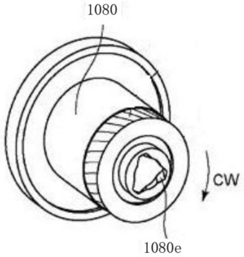
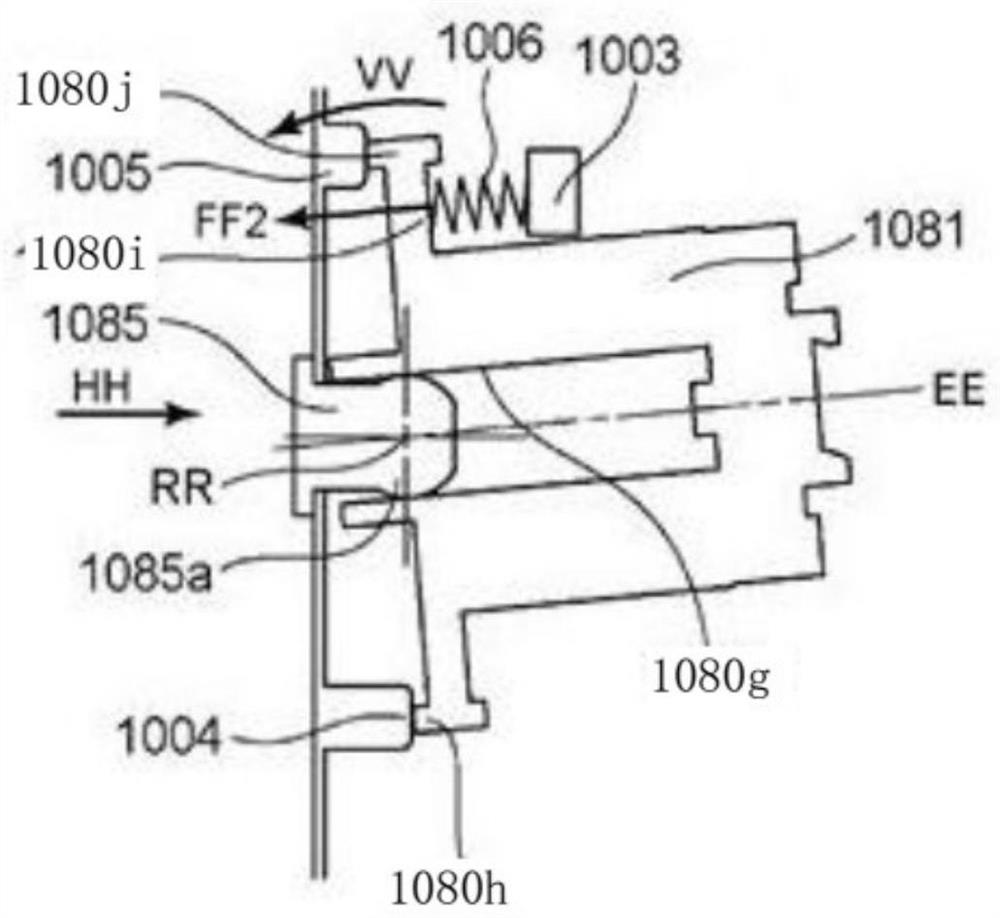
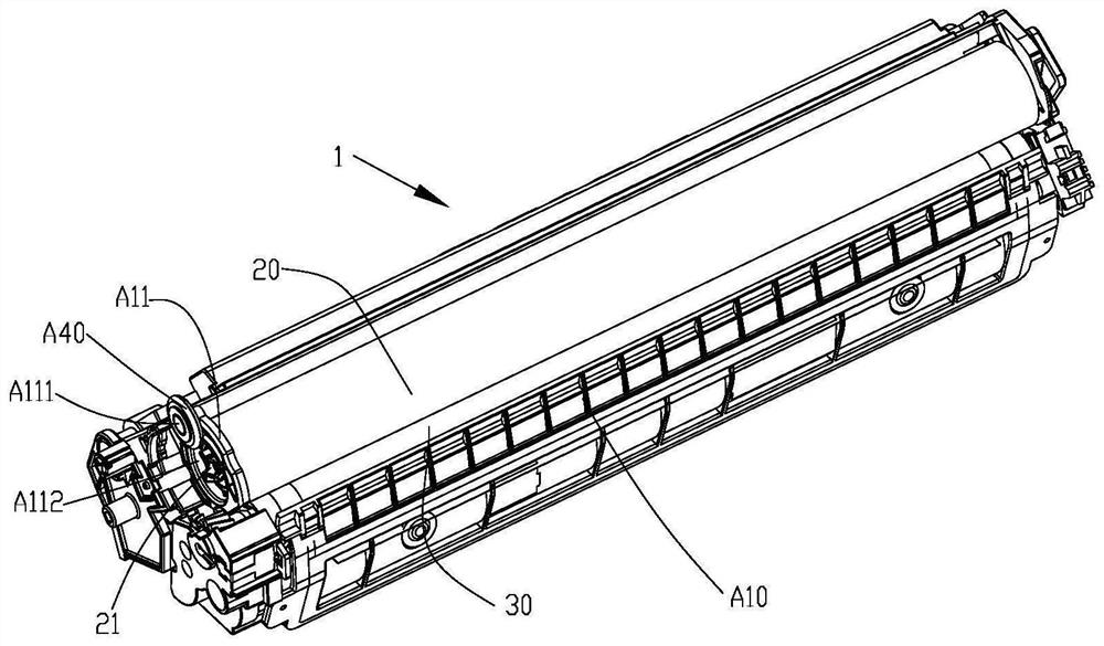
[0328] An embodiment of the present application provides an electronic imaging device, which includes a process box 1 , a driving unit 1080 and a driving unit protective cover 1081 , and the driving unit protective cover 1081 is disposed outside the driving unit 1080 .

[0329] The electronic imaging device may be a printer, a copier, an all-in-one scanning and copying machine, etc., which is not limited here. The following uses a printer as an example to describe the solution. The process cartridge may be a toner cartridge, an ink cartridge, or the like.

[0330] The processing box is generally composed of a toner bin unit and a waste toner bin unit. The toner bin unit includes a developing roller, a powder outlet knife, a powder feeding roller and a stirring frame, etc., and the waste toner bin unit includes a photosensitive drum, a charging roller, and a cleaning blade, etc. . The process box usually also includes a developer, and a power receiving unit for receiving exte...

Embodiment 2

[0339] Another process cartridge is provided in this embodiment, and the unspecified parts are the same in structure as the process cartridge in the first embodiment.

[0340] Such as Figure 7 and Figure 8As shown, the process box 1 also includes a movable positioning member B50, which is movably arranged on the bracket B11 and located at the same end as the power receiving unit 21, and the positioning member B50 can be displaced in a first direction relative to the bracket B11, Wherein, the first direction is the height extending direction of the process box ( Figure 8 in the Z direction). Further, the bracket B11 is provided with a sliding slot B15, which may be a rectangular sliding slot or a circular sliding slot, or other regular or irregular sliding slots, which are not limited here. The positioning member B50 is slidably disposed on the chute B15, so that the locating member B50 can move along the chute B15 relative to the box body.

[0341] When the process box ...

Embodiment 3

[0345] This embodiment provides another kind of pressing member, which is a further improvement on the basis of the second embodiment. The unexplained parts are the same as those in the foregoing embodiments, and will not be repeated for brevity.

[0346] like Figure 9 and Figure 10 As shown, the process box 1 also includes a movable positioning piece C50 and an elastic stretching piece C60. The positioning piece C50 is arranged on the bracket C11 and is located at the same end of the box body as the power receiving unit 21, and the positioning piece C50 is connected through the elastic stretching piece F60. The positioning member C50 is fixed to the bracket C11 so that it can move relative to the process cartridge body. The process box 1 also includes a pressing member C40, which is connected to the bracket C11 through a connecting rod C70. Specifically, the pressing member C40 is a gear, and the outer surface of the gear is a guiding pressing surface.

[0347] When the p...


PUM


Abstract

The invention provides a processing box. The processing box is detachably installed in an electronic imaging device. The processing box comprises a box body; the photosensitive drum is rotatably arranged on the box body; the power receiving unit is arranged at one end of the photosensitive drum, and the power receiving unit is used for being matched with the driving unit; the force applying unit is arranged on the box body, the force applying unit and the power receiving unit are located at the same end, and the force applying unit is used for applying acting force to the driving unit pushing piece, so that the driving unit is adjusted to be in a straightening state from an inclined state after losing the support of the driving unit pushing piece. And the transmission unit is meshed with or separated from the power receiving unit. According to the processing box and the electronic imaging device provided by the invention, the driving unit loses the support of the driving unit pushing piece to be engaged with or separated from the power receiving unit through the force application unit, so that rapid engagement is facilitated.

Description

technical field [0001] This application relates to the field of laser printing, and in particular to process cartridges. Background technique [0002] In the prior art, a process cartridge can be detachably mounted on an electronic image forming apparatus. The electronic imaging device is provided with a driving unit that outputs a rotational driving force. The process box generally includes a power receiving unit, a developing unit, a developer, a powder control unit, and a housing for accommodating the above units. In addition, according to different types of process box structures, a photosensitive unit, a charging unit, a cleaning unit and Stirring unit etc. The power receiving unit of the process box is arranged at one end of the process box along the axial direction of the developing unit. After the power receiving unit is engaged with the drive unit in the electronic imaging device, the rotating driving force is transmitted to the process box, and finally the proces...

Claims


Application Information

Patent Timeline
Patent Type & Authority Applications(China)
IPC IPC(8): G03G21/18
CPCG03G21/1814G03G21/1647G03G21/1857G03G15/0896
Inventor 罗琴曾丽坤丁戈明曹建新戴曙春贾志铮吴连俊虞文俊刘卫臣梁祺杰马海龙张为志彭庆菲
Owner NINESTAR CORP
Why Eureka
Try Eureka