Novel integrated oil-water separation device

An oil-water separation device and centrifugal separation technology are applied in the direction of liquid separation, separation method, grease/oily substance/suspton removal device, etc., which can solve the problems of large energy and chemical consumption, complex equipment structure, expensive equipment, etc., to achieve Easy to operate, easy to process, and easy to popularize and apply

Active Publication Date: 2013-12-04
GUANGDONG UNIV OF PETROCHEMICAL TECH +1
View PDF5 Cites 0 Cited by
  • Summary
  • Abstract
  • Description
  • Claims
  • Application Information

AI Technical Summary

Problems solved by technology

The disadvantage is that the operating cost is high, and it needs to consume a lot of energy and chemicals; the equipment price is relatively expensive, the equipment structure is complicated, and it is equipped with devices such as pressurization and dosing.

Method used


Image

  • Novel integrated oil-water separation device
  • Novel integrated oil-water separation device

Examples


Embodiment Construction

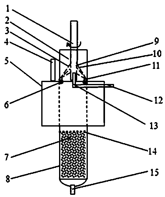
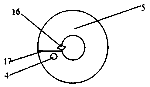
[0011] refer to figure 1 and figure 2 , the integrated oil-water separation device provided by the present invention includes two concentric inner and outer cylinders, the inner cylinder constitutes the centrifugal separation zone 2 and the adsorption separation zone 8 from top to bottom, and the inner and outer cylinders form the annulus gravity settlement Separation zone 5; Gravity sedimentation separation zone 5 has partition plate 17, the upper part of one side of the partition plate 17 has oil-water mixture inlet 4, and the other side has water outlet 16 entering centrifugal separation zone 2; Centrifugal separation zone 2 has oil-water mixture inlet 4; The pipe 13 is connected to the oil discharge port 12, and there is a discharge port 15 at the bottom of the adsorption area 8.

[0012] The centrifugal separation zone 2 is composed of a rotor part 1 and a stator part 6 with uniformly distributed balls fixed horizontally on the inner wall of the inner cylinder, wherein ...


PUM

PropertyMeasurementUnit
porosityaaaaaaaaaa
porosityaaaaaaaaaa

Abstract

The invention discloses a novel integrated oil-water separation device, comprising an inner circular barrel and an outer circular barrel which are concentric, wherein the inner circular barrel forms a centrifugal separation area (2) and an adsorptive separation area (8) from top to bottom, and the inner circular barrel and the outer circular barrel form an annular-space gravity-settling separation area (5); the gravity-settling separation area (5) is provided with a clapboard, an oil-water mixture inlet (4) is formed on the upper part of one side of the clapboard, and a water through port for entrance in the centrifugal separation area (2) is formed at the other side; and the centrifugal separation area (2) is provided with an oil discharge port (12), and a water drainage port (15) is formed on the bottom of the adsorptive separation area (8). The novel integrated oil-water separation device disclosed by the invention has the advantages of being high in oil-water separation efficiency, simplicity in machining, as well as simplicity and convenience in operation by coupling a gravity principle with a centrifugal and adsorptive separation principle.

Description

technical field [0001] The invention relates to a device for treating oily waste water, in particular to an integrated oil-water separation device. Background technique [0002] According to the state of oil substances in water, they can be divided into floatable oil, dispersed oil, emulsified oil and dissolved oil. The current oil-water separation methods mainly include gravity separation, centrifugal separation and air flotation separation. Both gravity and centrifugal separation use the difference in density between oil and water to separate oil and water under the action of gravity and centrifugal force. The most commonly used equipment for gravity separation is the grease trap. The oily wastewater flows in from one end of the pool and flows through the pool body at a relatively small flow rate. During the flow, the oil particles with a density less than water rise to the water surface, and the water flows from the pool The other end flows out, and the oil-water separa...

Claims


Application Information

Patent Timeline
Patent Type & Authority Patents(China)
IPC IPC(8): C02F9/02C02F1/40C02F1/28C02F1/38
Inventor 周如金米世伍邱松山赵子牛钟华文聂丽君谢颖
Owner GUANGDONG UNIV OF PETROCHEMICAL TECH
Why Eureka
Try Eureka