
Pallet and chemical vapor deposition equipment with pallet

A technology of chemical vapor deposition and trays, which is applied in the field of microelectronics, can solve the problems of uneven heating temperature of trays, achieve surface temperature balance, reduce temperature differences, and improve process requirements.

Active Publication Date: 2014-12-17
BEIJING NAURA MICROELECTRONICS EQUIP CO LTD
View PDF5 Cites 0 Cited by
  • Summary
  • Abstract
  • Description
  • Claims
  • Application Information

AI Technical Summary

Problems solved by technology

[0004] The object of the present invention is to at least solve one of the above-mentioned technical defects, especially the problem of uneven heating temperature of the tray

Method used


Image

  • Pallet and chemical vapor deposition equipment with pallet
  • Pallet and chemical vapor deposition equipment with pallet
  • Pallet and chemical vapor deposition equipment with pallet

Examples


Embodiment Construction

[0028] Embodiments of the present invention are described in detail below, examples of which are shown in the drawings, wherein the same or similar reference numerals designate the same or similar elements or elements having the same or similar functions throughout. The embodiments described below by referring to the figures are exemplary only for explaining the present invention and should not be construed as limiting the present invention.

[0029] In describing the present invention, it should be understood that the terms "longitudinal", "transverse", "upper", "lower", "front", "rear", "left", "right", "vertical", The orientation or positional relationship indicated by "horizontal", "top", "bottom", "inner", "outer", etc. are based on the orientation or positional relationship shown in the drawings, and are only for the convenience of describing the present invention and simplifying the description, rather than Nothing indicating or implying that a referenced device or elem...


PUM


Abstract

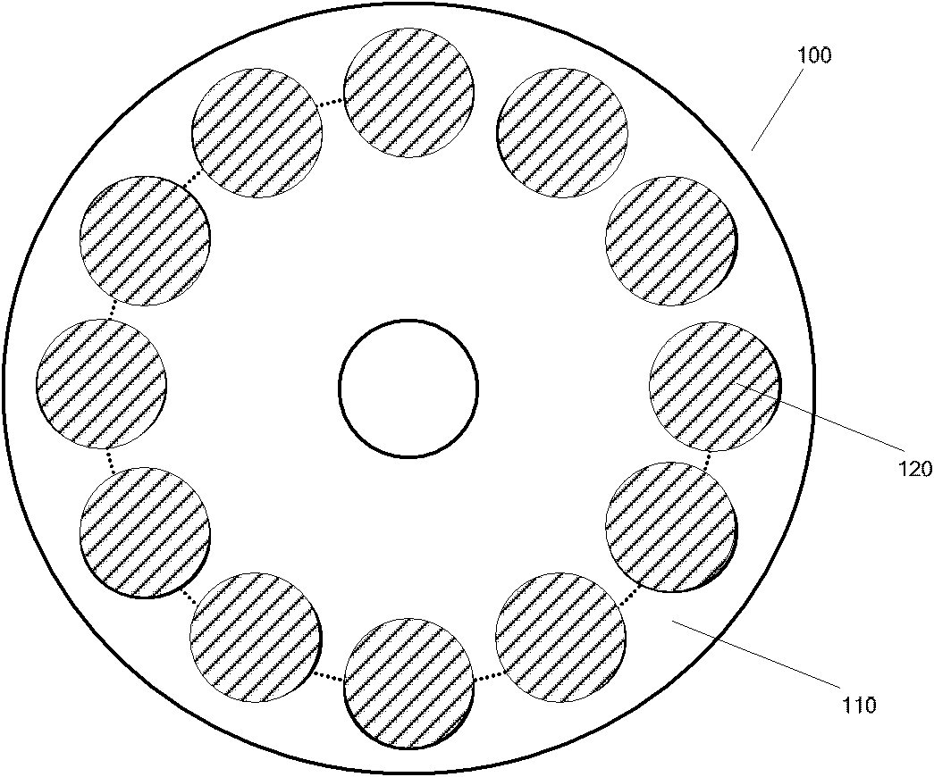
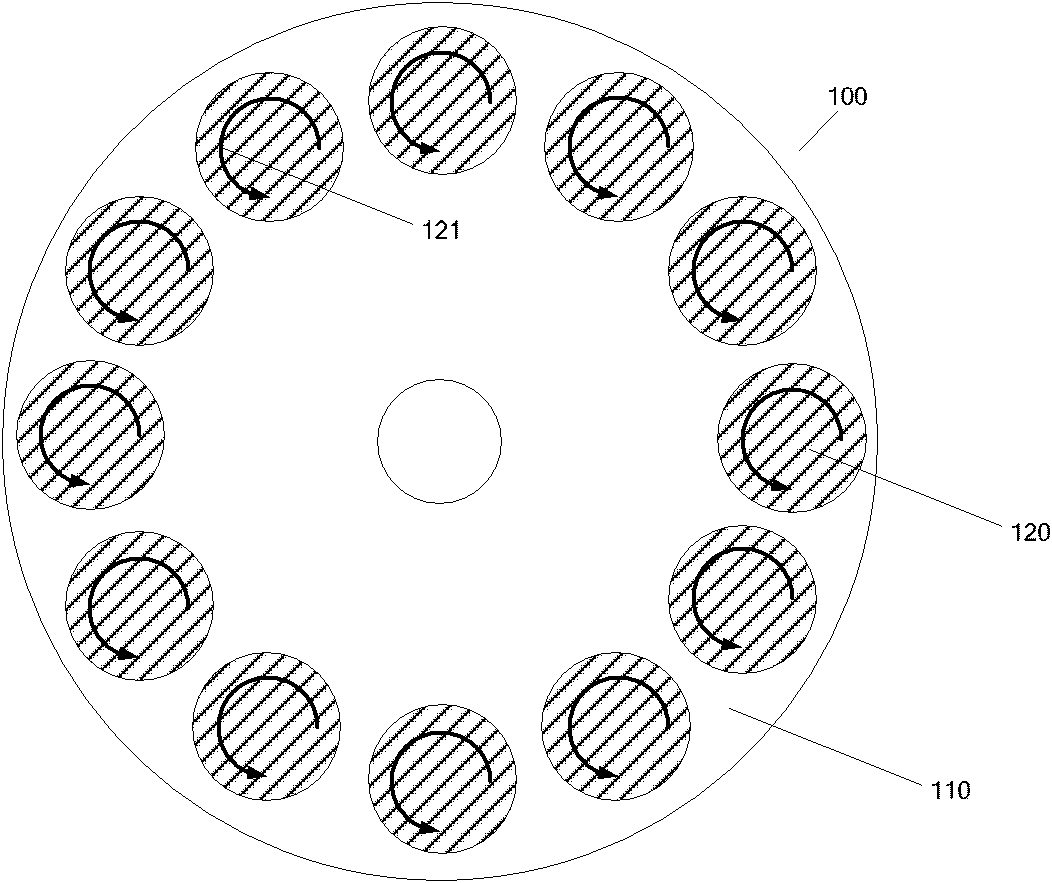
The invention brings forward a pallet, which comprises: a pallet body; a plurality of mounting grooves which are arranged along the circumference of the pallet body; and a plurality of small pallets, each small pallet correspondingly being arranged in one mounting groove, werein the pallet body is composed of an insulating material and the plurality of small pallets are composed of a heat conduction and electrically conductive material. The invention also brings forward chemical vapor deposition equipment with the above pallet. According to the chemical vapor deposition equipment provided by the invention, as the turning radius of induced-current is becoming smaller, the surface temperature of the pallet is more uniform, thus raising temperature homogeneity of a substrate processed by the chemical vapor deposition equipment. In addition, the pallet is simply designed and is easy to realize.

Description

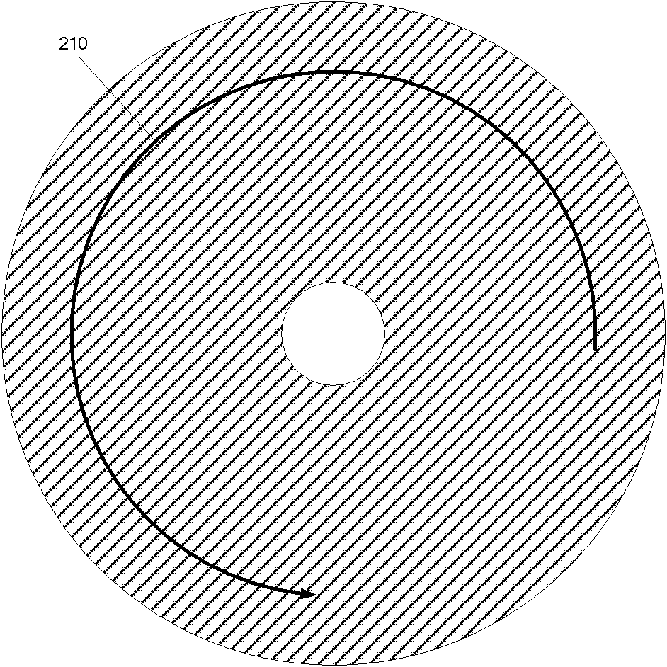
technical field [0001] The invention relates to the technical field of microelectronics, in particular to a tray and a chemical vapor deposition device with it. Background technique [0002] The temperature uniformity of MOCVD (metal organic compound chemical vapor deposition), especially the temperature uniformity on the tray carrying the substrate, plays a very important role in the process performance. In order to achieve this temperature uniformity, various manufacturers use different heating methods and corresponding Tray structure. For example, in the reaction chamber of the existing shower head structure, resistance wires are used to heat the entire large graphite tray, and the temperature uniformity of the tray is realized through partitioned resistance wires. The existing planetary structure uses induction to heat the entire large graphite tray, and the large tray carries a small tray that can rotate, and achieves better temperature uniformity in the small tray thr...

Claims


Application Information

Patent Timeline
Patent Type & Authority Patents(China)
IPC IPC(8): C23C16/458
Inventor 徐亚伟
Owner BEIJING NAURA MICROELECTRONICS EQUIP CO LTD
Learn More