
Apparatus for, and method of, roll forming sheets of high refractive index glass

a technology of refractive index glass and apparatus, which is applied in the field of apparatus for and method of roll forming sheets of high refractive index glass, can solve the problems of warpage, fracture of glass ribbons, and suboptimal total thickness variation of separated glass sheets

Active Publication Date: 2022-05-19
CORNING INC
View PDF6 Cites 0 Cited by
  • Summary
  • Abstract
  • Description
  • Claims
  • Application Information

AI Technical Summary

Benefits of technology

The present patent addresses the problem of fracturing or suboptimal thickness variation and warp in glass sheets separated from a ribbon of glass. The method involves reducing horizontal temperature variability of the ribbon of glass before it cools to a glass transition temperature, controlling the cooling rate of the ribbon of glass while it moves vertically downward within a setting zone, and using heat loss reduction elements to face the central portion of the ribbon of glass. These measures help to prevent fracture and ensure consistent thickness and quality of the glass sheets.

Problems solved by technology

However, it has been discovered that there is a further problem in that continuously roll forming the ribbon of glass of the high refractive index glass can result in fracture of the ribbon of glass or in separated glass sheets that have suboptimal total thickness variation and warp.

Method used


Image

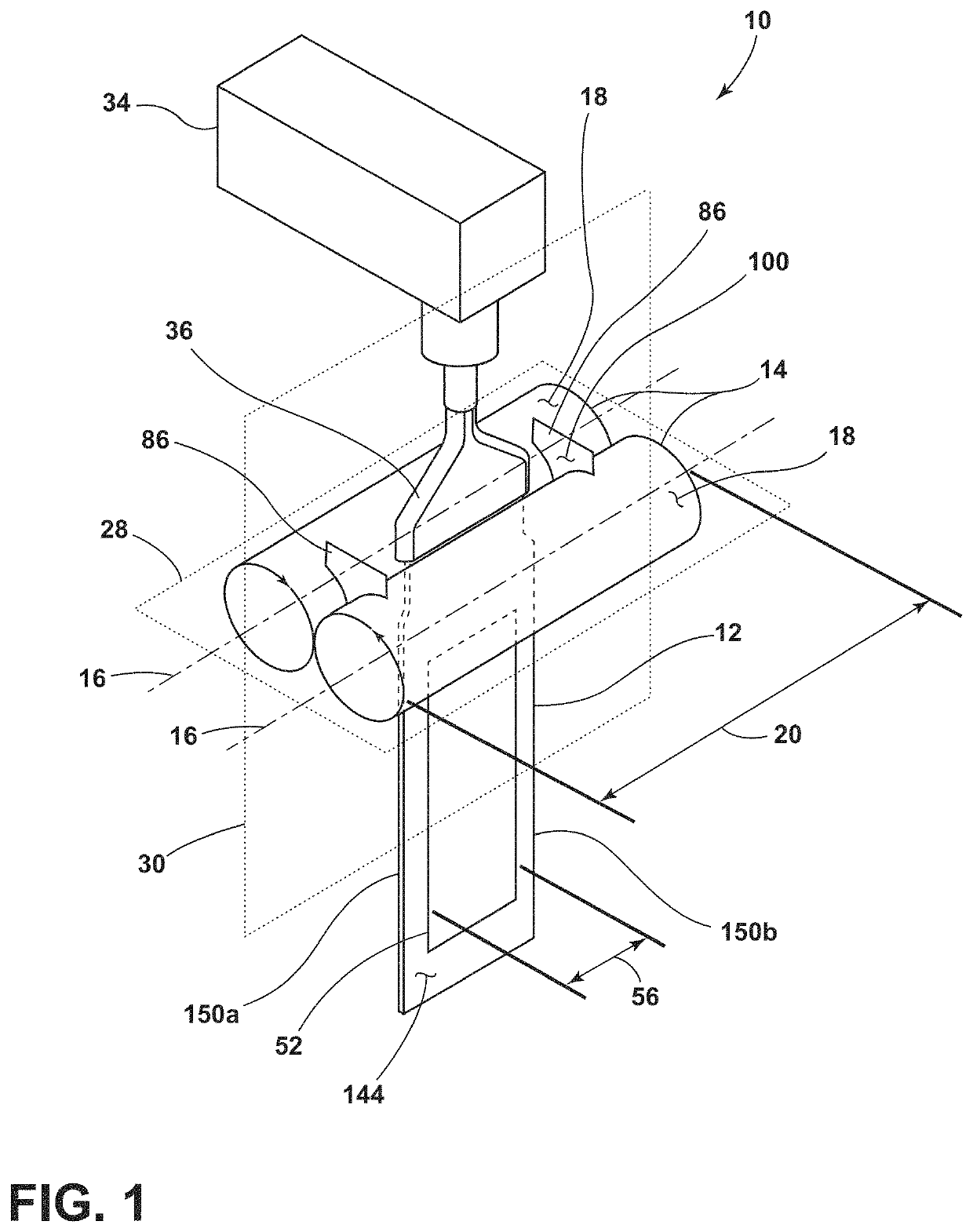
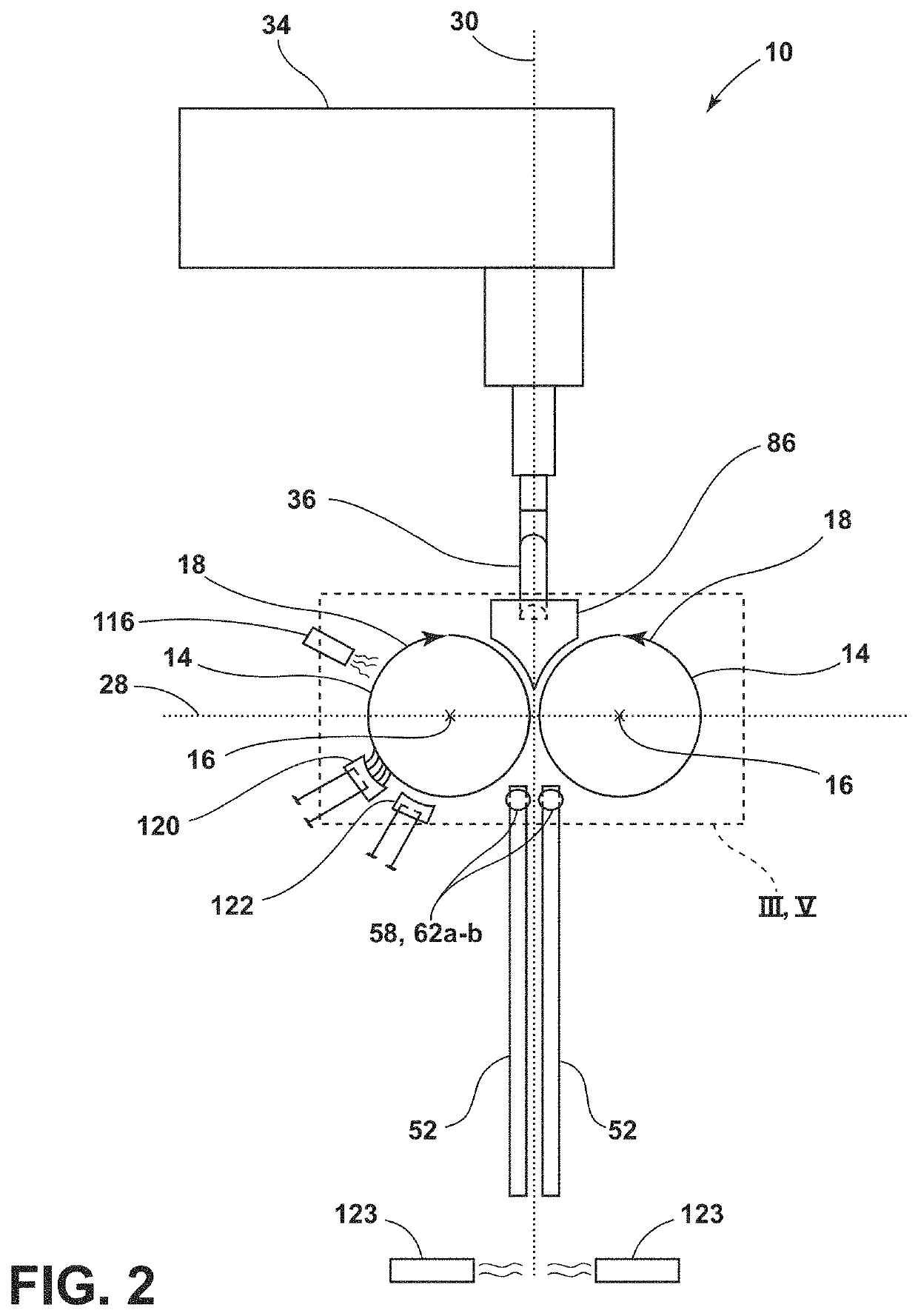
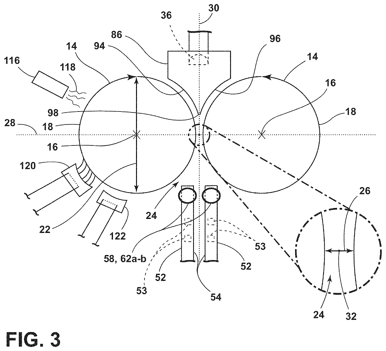
  • Apparatus for, and method of, roll forming sheets of high refractive index glass
  • Apparatus for, and method of, roll forming sheets of high refractive index glass
  • Apparatus for, and method of, roll forming sheets of high refractive index glass

Examples


example 1

[0149] For Example 1, two ribbons of glass were formed using two different sets of forming rollers—a first set having an outer diameter of 4 inches (˜101 mm) and a second set having an outer diameter of 2 inches (˜51 mm). A single tube outlet feed device was utilized to supply the stream of molten glass to the gap between the sets of forming rollers to form the puddle of molten glass. The same flow rate of molten glass was delivered to each of the sets of forming rollers. No dams were utilized to adjust the width or the height of the puddle of molten glass.

[0150]With the set of forming rollers with the 4-inch outer diameter, a ribbon of glass was produced having a thickness of 6.1 mm and a width of 89 mm. With the set of forming rollers with the 2-inch outer diameter and the same flow rate of molten glass, (i) a ribbon of glass was produced having a smaller thickness of 4.6 mm and slightly larger width of 106 mm, and (ii) a ribbon of glass was produced having a larger width of 140 m...

example 6

[0158] For Example 6, a single tube outlet feed device was utilized to supply the stream of molten glass to the gap between the forming rollers to form the puddle of molten glass. No dams were utilized to adjust the width or the height of the puddle of molten glass. The forming rollers formed a ribbon of glass from the puddle of molten glass. A pair of pinching rollers were utilized to reduce the thickness of the second lateral edge of the ribbon of glass but not the first lateral edge of the ribbon of glass. The pair of pinching rollers reduced the thickness of the ribbon of glass at the second lateral edge from 3 mm to 2.26 mm. The thickness of the ribbon of glass near the second lateral edge was about 2.2 mm. The thickness of some portions of the ribbon of glass were reduced to 1.9 mm.

[0159]The horizontal temperature profile was measured at a horizontal position before the pair of pinching rollers reduced the thickness of the second lateral edge of the ribbon of glass. The horizo...


PUM

PropertyMeasurementUnit
Temperatureaaaaaaaaaa
Fractionaaaaaaaaaa
Fractionaaaaaaaaaa

Abstract

A method of forming a glass sheet comprises: (a) forming a ribbon of glass from molten glass with a pair of forming rollers; (b) reducing horizontal temperature variability of the ribbon of glass to be 10° C. or less across 80 percent of an entire width of the ribbon of glass before the ribbon of glass cools to a glass transition temperature; (c) controlling a cooling rate of the ribbon of glass while the ribbon of glass moves vertically downward within a setting zone such that the ribbon of glass has a first average cooling rate before the ribbon of glass cools to the glass transition temperature and a second average cooling rate after the ribbon of glass cools to the glass transition temperature, the first average cooling rate being less than the second average cooling rate; and (d) separating a glass sheet from the ribbon of glass.

Description

[0001]This Application claims priority under 35 USC § 119(e) from U.S. Provisional Patent Application Ser. No. 63 / 113,507[0002]filed on Nov. 13, 2020[0003]which is incorporated by reference herein in its entirety.BACKGROUND OF THE INVENTION[0004]An augmented reality system adds computer-generated imagery to a real visual scene observed by a user of the system. The augmented reality system typically includes an optical system that is configured to allow viewing of an object or scene, while adding computer-generated imagery to the actual object or scene that is being viewed directly. The optical system can utilize a light guide, which can be made of high refractive index glass, to project the computer-generated image into the user's field of view. Deviations in the geometry of the light guide can reduce the quality of the images guided through the light guide and displayed for the user. For example, the total thickness variation and the warp of the light guide should be minimized to a...

Claims


Application Information

Patent Timeline
IPC IPC(8): C03B17/06
CPCC03B17/067C03B17/068C03B17/064C03B25/02C03C3/062C03C3/095C03B25/12C03C1/00C03B25/025
Inventor BRESSLER, DOUGLAS DALEDENEKA, DAVID ALANGERRISH, MICHAEL CHARLESJENNINGS, DOUGLAS HULLKUNITAKE, MIKI EUGENELOCK, WILLIAM EDWARDMUDIRAJ, SHYAM PRASADPARTRIDGE, NEIL EUGENEPAYNE, JEREMY NATHANPROULX, II, EUGENE ROLANDSUTTON, RYAN CHRISTOPHERTARCZA, STEVEN HOWARD
Owner CORNING INC
Learn More