
Vacuum coating cavity and vacuum coating equipment

A technology of vacuum coating and vacuum cavity, applied in gaseous chemical plating, metal material coating process, coating and other directions, can solve problems such as poor coating quality

Active Publication Date: 2022-08-09
广东华升纳米科技股份有限公司
View PDF7 Cites 0 Cited by
  • Summary
  • Abstract
  • Description
  • Claims
  • Application Information

AI Technical Summary

Problems solved by technology

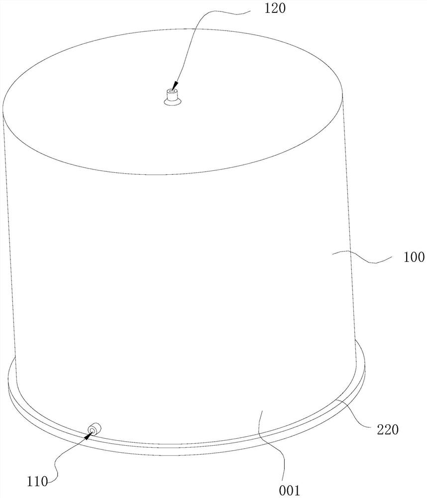
[0005] Based on this, it is necessary to provide a vacuum coating chamber and vacuum coating equipment for the problem of poor coating quality of the vacuum coating device

Method used


Image

  • Vacuum coating cavity and vacuum coating equipment
  • Vacuum coating cavity and vacuum coating equipment
  • Vacuum coating cavity and vacuum coating equipment

Examples


Embodiment Construction

[0028] In order to make the above objects, features and advantages of the present invention more clearly understood, the specific embodiments of the present invention will be described in detail below with reference to the accompanying drawings. In the following description, numerous specific details are set forth in order to provide a thorough understanding of the present invention. However, the present invention can be implemented in many other ways different from those described herein, and those skilled in the art can make similar improvements without departing from the connotation of the present invention. Therefore, the present invention is not limited by the specific embodiments disclosed below.

[0029] In the description of the present invention, it should be understood that the terms "center", "longitudinal", "lateral", "length", "width", "thickness", "upper", "lower", "front", " Back, Left, Right, Vertical, Horizontal, Top, Bottom, Inner, Outer, Clockwise, Countercl...


PUM


Abstract

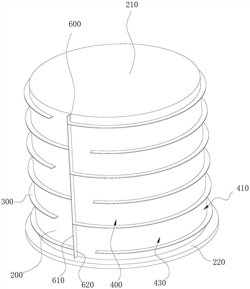
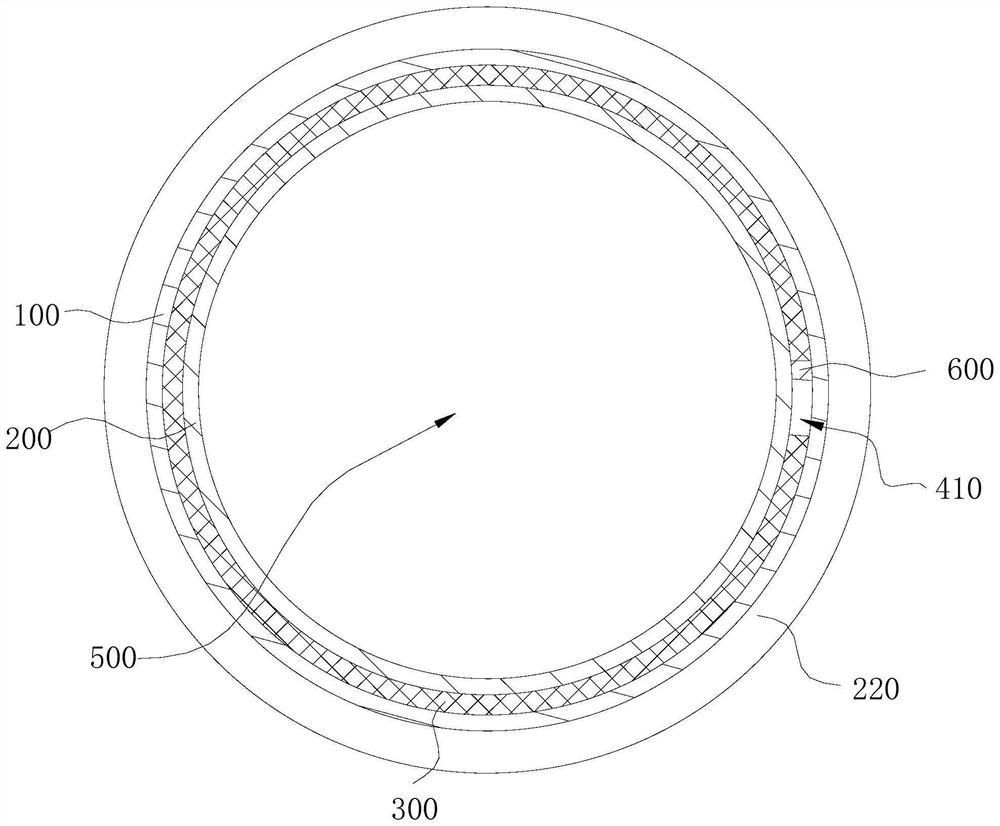
The invention relates to a vacuum coating cavity and vacuum coating equipment. The vacuum coating cavity comprises a vacuum cavity body and a cooling cavity body, the cooling cavity body is arranged around the periphery of the vacuum cavity body, the cooling cavity body and the vacuum cavity body are not communicated with each other, the vacuum cavity body comprises a plurality of partition pieces, the partition pieces are arranged in the cooling cavity body at intervals and divide the cooling cavity body into a plurality of flow channels, and the flow channels are communicated with the cooling cavity body. The multiple flow channels are sequentially communicated to form a cooling channel, the cooling cavity is provided with a liquid inlet and a liquid outlet, one end of the cooling channel is communicated with the liquid inlet, and the other end of the cooling channel is communicated with the liquid outlet. The cooling medium can be distributed in the vacuum coating cavity of the cooling cavity along the cooling flow channel, so that the problem that the surface temperature difference of the vacuum coating cavity is large due to non-uniform distribution of the cooling medium is solved, and the vacuum coating quality is improved.

Description

technical field [0001] The invention relates to the technical field of vacuum coating equipment, in particular to a vacuum coating chamber and vacuum coating equipment. Background technique [0002] Chemical vapor deposition (CVD) refers to a method in which chemical gases or vapors react on surfaces to synthesize coatings or nanomaterials. During chemical vapor deposition, the surface of the workpiece can be plated with a film (or coating) of the corresponding material according to actual needs. For example, in some applications, a diamond coating can be applied to the surface of the workpiece. [0003] At present, when coating the surface of the workpiece, a vacuum coating device is usually used for coating. The vacuum coating device includes a vacuum coating chamber, and the vacuum coating chamber has a vacuum chamber. When using a vacuum coating device, the workpiece is placed in a vacuum chamber for coating. [0004] However, when the current vacuum coating device c...

Claims


Application Information

Patent Timeline
IPC IPC(8): C23C16/44C23C16/46
CPCC23C16/44C23C16/463Y02E60/10
Inventor 杨恺林海天李立升刘贵董得平
Owner 广东华升纳米科技股份有限公司
Learn More