A washing machine inner tub with self-cleaning tub wall function and washing machine
A washing machine and self-cleaning technology, applied in the field of washing machines, can solve the problems of small gaps, reduced particles, and difficult water flow to wash away, and achieve the effects of increased fluidity, simple structure, and reduced dirt
- Summary
- Abstract
- Description
- Claims
- Application Information
AI Technical Summary
Problems solved by technology
Method used
Image
Examples
Embodiment 1
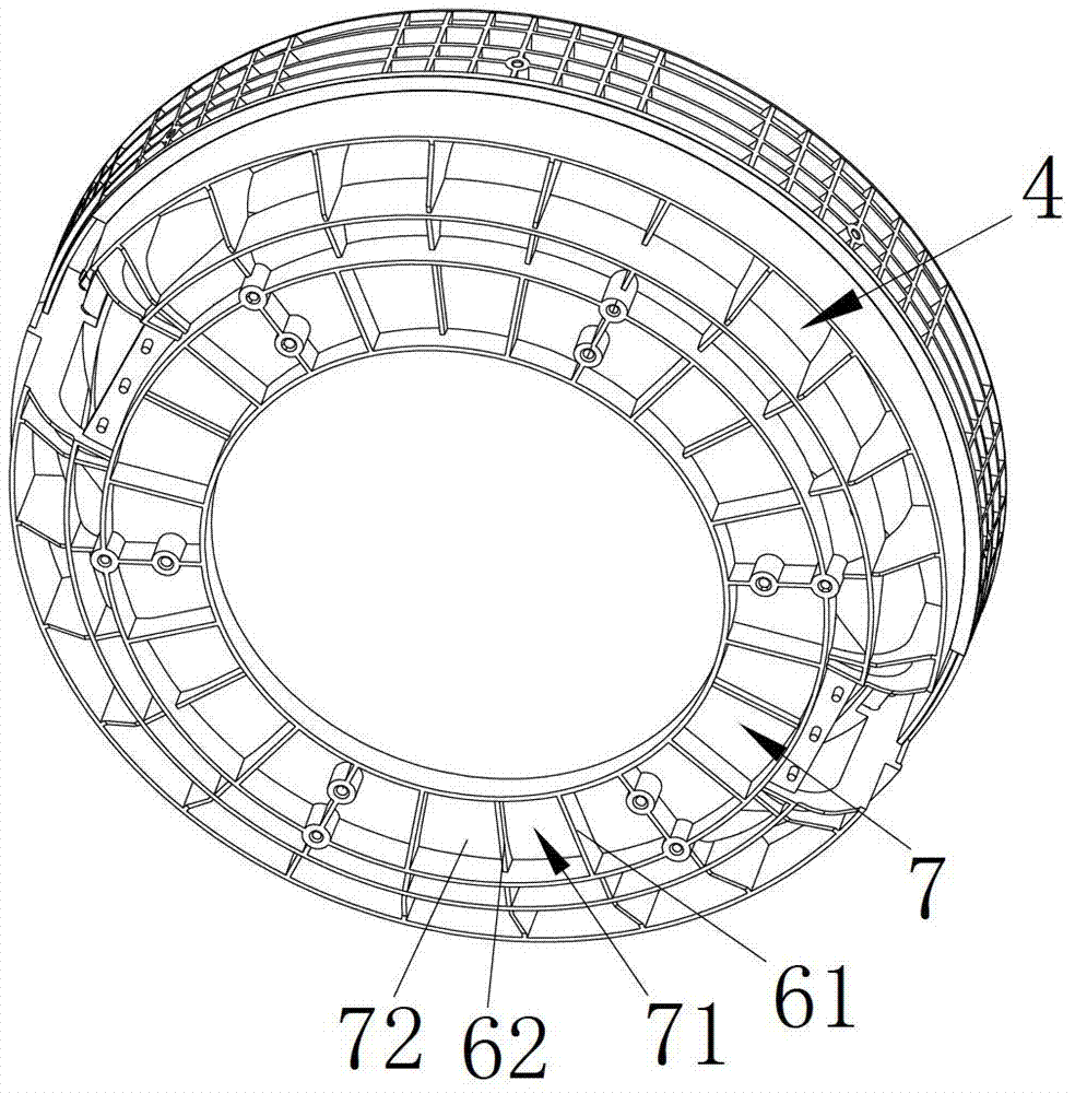
[0039] Such as image 3 As shown, the groove space 7 described in this embodiment includes a large groove space 71 surrounded by external reinforcing ribs 61 and a small groove space 72 formed by dividing and forming internal reinforcing ribs 62 in the large groove space 71. The height of the ribs 61 is greater than the height of the internal reinforcing ribs 62 . This structure can make the cleaning particles move in a variety of ways in the groove space, the number of collisions is more, the cleaning effect is better, and the strength of the bottom of the inner bucket will not be reduced.
[0040] In this embodiment, the distance between the external reinforcing ribs 61 is at least 20 cm, and the height of the internal reinforcing ribs 62 is no more than 5 mm.
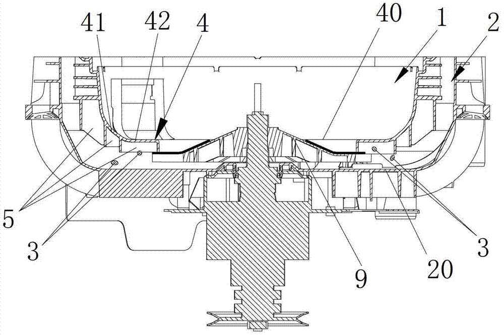
[0041] The inner barrel bottom 4 of the present invention is a hollow ring structure, and the hollow position 40 is provided with a particle blocking structure (refer to Figure 5 with Image 6 ).
Embodiment 2
[0043] Such as Image 6 As shown, the groove space 7 is surrounded by multiple sections of radial reinforcement ribs 63 and multiple sections of circumferential reinforcement ribs 64 , which are distributed under the annular inner barrel bottom 4 .
[0044] Since the bottom of the inner barrel is circular, the distance between two adjacent radial ribs becomes smaller as it approaches the center of the circle. In order to ensure the sufficient movement of the cleaning particles, two adjacent radial ribs 63 forming the groove space 7 are required. The angle α between them is 12°-30°, and the distance d between two radially adjacent ribs 64 in the circumferential direction is 1 / 6-1 / 2 times the radius R of the inner barrel bottom, preferably, close to the inner barrel The distance between the two circumferential reinforcing ribs 64 at the bottom hollow position 40 is the largest.
Embodiment 3
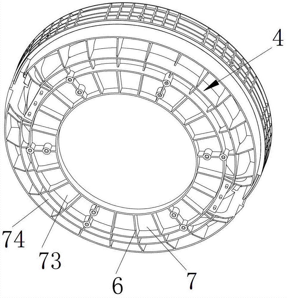
[0046] Such as figure 1 As shown, the annular inner barrel bottom 4 in this embodiment includes an arc-shaped portion 41 transitioning from the inner barrel wall and a gentle portion 42 extending toward the center, and the distance between the lower reinforcing rib 6 and the outer barrel becomes smaller radially toward the center. The area corresponding to the groove space 73 below the gentle portion 42 is greater than the area corresponding to the groove space 74 below the arc portion 41 (see figure 2 ), the height of the ribs constituting the groove space 73 below the flat portion is smaller than the height of the ribs constituting the groove space 74 below the arc portion.
PUM
 Abstract
Description
Claims
Application Information
 - R&D
- Intellectual Property
- Life Sciences
- Materials
- Tech Scout
- Unparalleled Data Quality
- Higher Quality Content
- 60% Fewer Hallucinations
Browse by: Latest US Patents, China's latest patents, Technical Efficacy Thesaurus, Application Domain, Technology Topic, Popular Technical Reports.
© 2025 PatSnap. All rights reserved.Legal|Privacy policy|Modern Slavery Act Transparency Statement|Sitemap|About US| Contact US: help@patsnap.com


