Opened debris flow blocking dam set

A kind of debris flow, open technology, applied in the direction of coastline protection, jetty, bank pier, etc., can solve the problems such as the loss of the retaining function of the dam, the weakening of the retaining dam, and the amplification of the energy of the debris flow, so as to achieve good retaining effect and low adverse pressure. , the effect of enhancing stability

Inactive Publication Date: 2012-10-17
LANZHOU UNIVERSITY
View PDF7 Cites 9 Cited by
  • Summary
  • Abstract
  • Description
  • Claims
  • Application Information

AI Technical Summary

Problems solved by technology

[0002] At present, most of the debris flow retaining dams are closed structures, and the dam body is provided with a number of drainage holes, and the solid matter in the debris flow is blocked in the storage area formed by the three sides of the dam body and the debris flow ditch wall; on the one hand, under the impact of debris flow Under normal circumstances, the drainage holes are easily blocked by solid sand or stones, thus losing the drainage effect; Unfavorable pressure, and the retaining function of the retaining dam will also be lost. When the debris flow occurs again, the retaining effect of the retaining dam will be significantly weakened
[0003] Once the debris flow causes part or all of the dam to collapse, the accumulation in the storage area provides a richer source for the debris flow, the velocity and flow of the debris flow increase sharply, and the erosion carrying capacity and destruction capacity are greatly improved. In the retaining dam project of cascaded buildings, the chain reaction produced after the upper retaining dam collapses causes the lower retaining dam to collapse, causing the energy of the debris flow to amplify step by step, thus causing huge damage

Method used


Image

  • Opened debris flow blocking dam set

Examples


Embodiment Construction

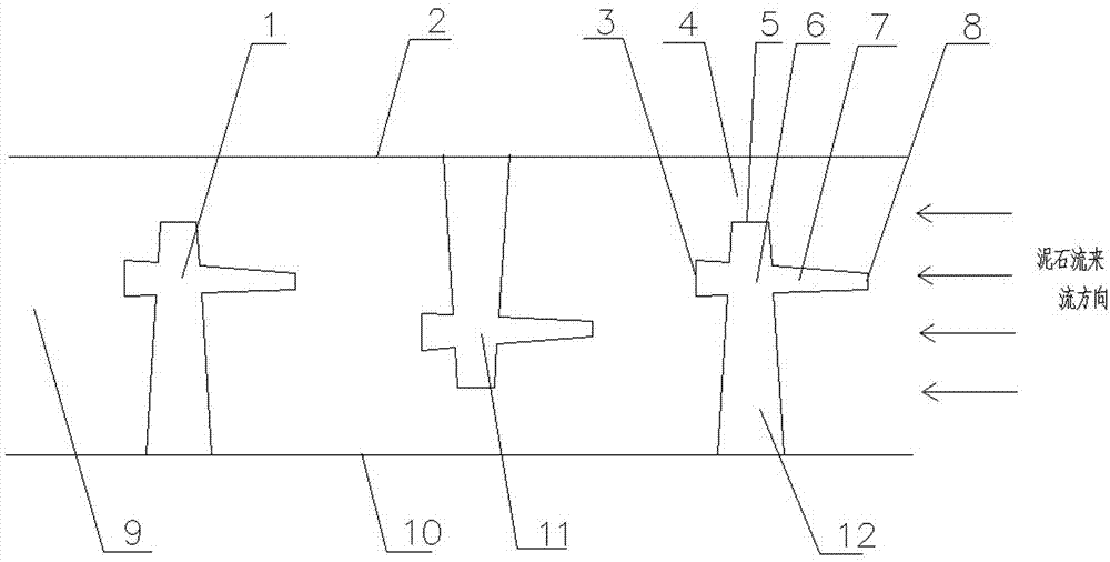
[0016] Such as figure 1 As shown, an open debris flow retaining dam group consists of three retaining dams 1, 6, and 11 which are located in the debris flow ditch 9 and have the same structure. Taking the retaining dam 6 as an example, the retaining dam 6 consists of the main dam 12 and An auxiliary dam 7 is formed; the debris flow ditch 9 has ditch walls 2 and 10, one end of the main dam 12 is connected to the ditch wall 10, and the other end is an open end 5, and an opening 4 is formed between the open end 5 and the ditch wall 2 to which it points. The main dam 12 and the auxiliary dam 7 form a cross-shaped structure, the auxiliary dam 7 is parallel to the ditch walls 2, 10 and the distance between the auxiliary dam 7 and the open end 5 of the main dam 12 is 1 / 3rd of the length of the main dam 12 1. The auxiliary dam 7 has a far end 8 and a proximal end 3 relative to the main dam 12, wherein the far end 8 of the auxiliary dam 7 points to the direction of the incoming debris ...


PUM


Abstract

The invention relates to an opened debris flow blocking dam set. The opened debris flow blocking dam set comprises at least two blocking dams; each blocking dam comprises a main dam and an auxiliary dam; one end of each main dam is connected with the ditch wall of a debris flow ditch, and the other end of each main dam is opened; each auxiliary dam is arranged near the main dam, and each auxiliary dam and the main dam form a T-shaped or crossed structure, and the one end of each auxiliary dam, which is far way from the main dam, points to the flow incoming direction of the debris flow; and the blocking dams are staggered along the debris flow ditch. According to the opened debris flow blocking dam set, multi-stage opening type design is adopted, impoundment and flow division are combined, debris flow is divided stage by stage, the flow speed and impact force of the debris flow are reduced stage by stage, and the damage of the debris flow is basically eliminated after multi-stage impoundment. The opened debris flow blocking dam set is simple in structure and safe and reliable, and debris flow deposit born by each stage of the dam applies small pressure to the dam; a good impoundment effect can be achieved; convenience is brought to dredging, and due to the opening design, a dredging vehicle can shuttle back and forth among all the blocking dams to dredge conveniently.

Description

technical field [0001] The invention relates to a mud-rock flow retaining dam group, in particular to an open mud-rock flow retaining dam group with stable structure, good retaining effect and convenient dredging. Background technique [0002] At present, most of the debris flow retaining dams are closed structures, and the dam body is provided with a number of drainage holes, and the solid matter in the debris flow is blocked in the storage area formed by the three sides of the dam body and the debris flow ditch wall; on the one hand, under the impact of debris flow Under normal circumstances, the drainage holes are easily blocked by solid sand or stones, thus losing the drainage effect; Unfavorable pressure, and the retaining function of the retaining dam will also be lost. When the debris flow occurs again, the retaining effect of the retaining dam will be significantly weakened. [0003] Once the debris flow causes part or all of the dam to collapse, the accumulation i...

Claims


Application Information

Patent Timeline
Patent Type & Authority Applications(China)
IPC IPC(8): E02B3/06
Inventor 彭宁波张妮孙博言志信
Owner LANZHOU UNIVERSITY
Why Eureka
Try Eureka