Diesel engine sequential supercharging structure and control method thereof

A technology of successive supercharging and diesel engines, applied in mechanical equipment, combustion engines, machines/engines, etc., can solve problems such as controlled supercharger damage, compressor mechanical damage, surge, etc., to eliminate surge phenomenon, improve Conditions of use, the effect of avoiding the phenomenon of zero-flow speed

Inactive Publication Date: 2012-10-17
HARBIN ENG UNIV
View PDF6 Cites 17 Cited by
  • Summary
  • Abstract
  • Description
  • Claims
  • Application Information

AI Technical Summary

Problems solved by technology

[0003] During the operation of the diesel engine sequential supercharging system, when the controlled supercharger is out of operation, that is, when the gas valve and the air valve are closed, due to the influence of the moment of inertia, the controlled supercharger must have a certain speed, and at this time the compressed air The outlet of the compressor has been blocked by the air valve, that is, the compressor has a zero flow phenomenon under the condition of rotating speed, which will inevitably cause severe surge phenomenon, which will inevitably cause mechanical damage to the compressor
[0004] At present, the existing diesel engine sequential supercharging structure does not have a vent valve at the outlet of the controlled supercharger compressor, which will cause certain damage to the controlled supercharger during use.

Method used


Image

  • Diesel engine sequential supercharging structure and control method thereof

Examples


Embodiment Construction

[0013] The present invention is described in more detail below in conjunction with accompanying drawing example:

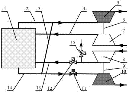
[0014] to combine figure 1 , diesel engine 1 of the present invention, A row intake manifold 4, A row exhaust manifold 2, B row intake manifold 13, B row exhaust manifold 14, basic supercharger 6, controlled supercharger 9, gas valve 11 , Air valve 12, deflation valve 15, exhaust connecting pipe 3, etc. One end of the purge valve 15 is connected to the outlet of the controlled supercharger compressor 8, and the other end is connected to the external atmosphere. One end of the gas valve 11 is connected to the inlet of the controlled supercharger turbine 10, and the other end is connected to the outlet of the B row exhaust main pipe 14. One end of the air valve 12 is connected to the inlet of the intake manifold 13 of row B, and the other end is connected to the outlet of the controlled supercharger compressor 8 . One end of the exhaust communication pipe 3 is co...


PUM


Abstract

The invention aims to provide a diesel engine sequential supercharging structure and a control method thereof. The diesel engine sequential supercharging structure comprises a diesel engine, air inlet pipes, exhaust pipes, turbochargers, an air vent valve, an air valve and a gas valve, the turbochargers comprises a basic turbocharger and a controlled turbocharger; the air inlet pipes comprise an A column of air inlet pipes, a B column of air inlet pipes, a compressor connected with the basic turbocharger and a compressor connected with the controlled turbocharger; the exhaust pipes comprise an A column of exhaust pipes, a B column of exhaust pipes, a turbine connected with the basic turbocharger and a turbine connected with the controlled turbocharger; the A column of exhaust pipes and the B column of exhaust pipes are communicated through exhaust connecting pipes; the gas valve is installed on the B column of exhaust pipes; the air valve and the air vent valve are installed on the B column of air inlet pipes; and the air vent valve is located between the air valve and the compressor of the controlled turbocharger. According to the invention, a phenomenon of zero flow with non-zero rotating speed of the compressor can be avoided; surge phenomenon of the superchargers can be eliminated; and usage conditions of the supercharger are improved effectively.

Description

technical field [0001] The invention relates to a diesel engine, specifically a camera supercharged diesel engine. Background technique [0002] Sequential supercharging technology is the first technology adopted by German MTU company. Its design is mainly to expand the working range of low compression ratio and high supercharging engine, increase the low-speed torque of the engine and reduce the fuel consumption rate during partial load operation. Its basic principle is to use multiple turbochargers, which are sequentially put into operation as the engine speed and load increase, so as to ensure that the working turbochargers are always running in the high-efficiency zone, so that the engine's The fuel consumption rate is low throughout the operating range, and the low-speed high-torque performance is good. [0003] During the operation of the diesel engine sequential supercharging system, when the controlled supercharger is out of operation, that is, when the gas valve an...

Claims


Application Information

Patent Timeline
Patent Type & Authority Applications(China)
IPC IPC(8): F02B37/007F02B37/12
CPCY02T10/144Y02T10/12
Inventor 杨传雷王银燕王贺春冯永明张鹏奇何清林
Owner HARBIN ENG UNIV
Why Eureka
Try Eureka