Measuring tool for rectifier channel and method for measuring rectifier channel

A rectifier and channel technology, applied in the field of rectifier channel measuring tools and measuring rectifier channels, can solve the problems of uncontrolled size and reduced channel area, and achieve the effects of improving performance, ensuring processing quality, and eliminating adverse effects

Active Publication Date: 2018-11-27
CHINA HANGFA CHANGZHOU LANXIANG MACHINERY CO LTD
View PDF7 Cites 0 Cited by
  • Summary
  • Abstract
  • Description
  • Claims
  • Application Information

AI Technical Summary

Problems solved by technology

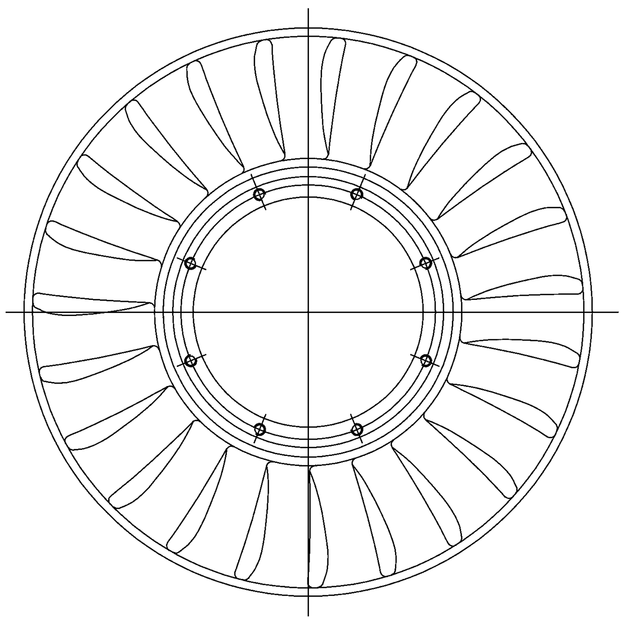
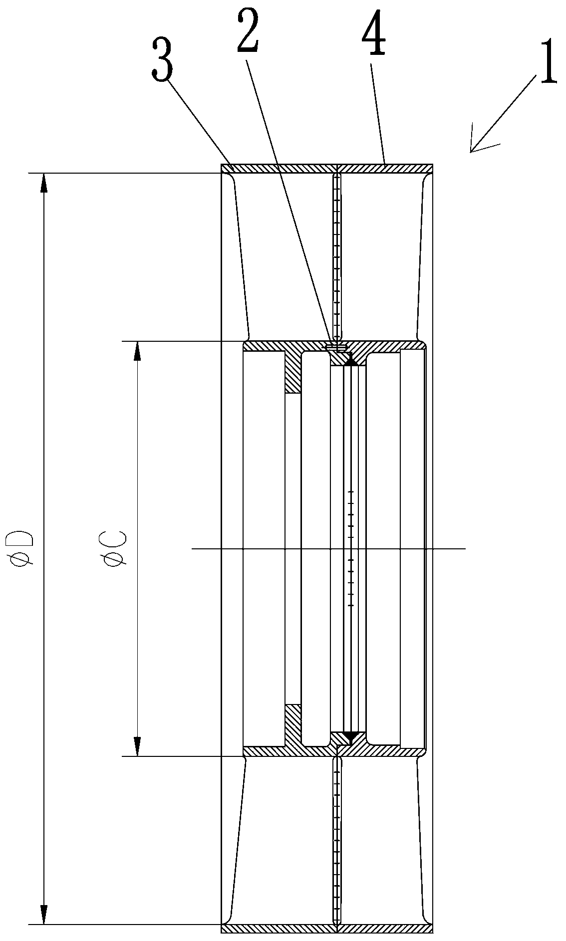
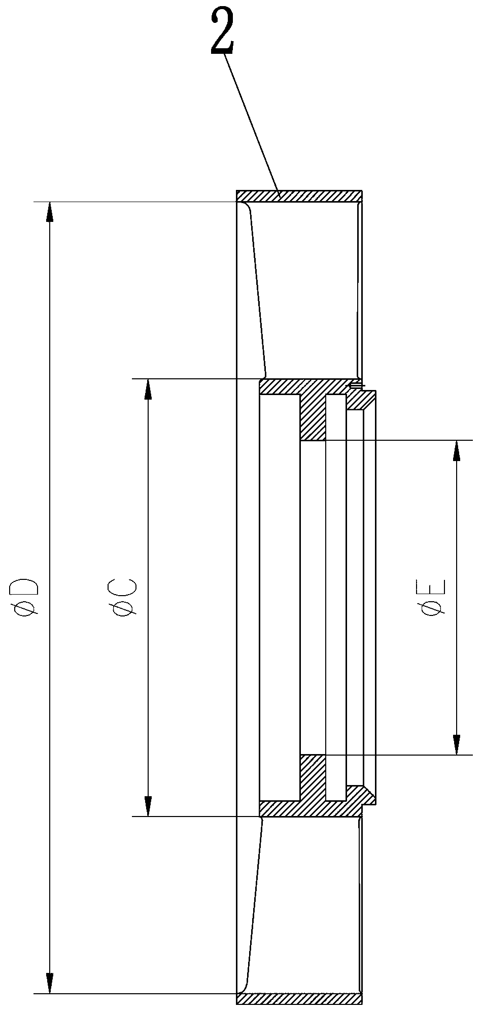
[0004] like Figures 1 to 2 , the front and rear rectifiers belong to the closed impeller, which is composed of 23 uniformly distributed blades and inner and outer hubs. The blade shape processing is measured by the sample, the channel bottom diameter φC size, the roundness error 0.3, and the cascade channel top diameter φD size Universal vernier caliper measurement, because the blade profile of the cascade channel is distributed along the φC and φD cylinder curves, the universal vernier caliper can only measure the mouth of the cylinder, the middle part cannot be detected, and the size cannot be controlled. The cylinder size is determined by Casting is guaranteed, but the actual blank cannot be done, and there is still a margin. Under the premise that the size of the bottom and top of the channel cannot be controlled, the area of ​​the channel will be reduced, which is inevitable

Method used


Image

  • Measuring tool for rectifier channel and method for measuring rectifier channel
  • Measuring tool for rectifier channel and method for measuring rectifier channel
  • Measuring tool for rectifier channel and method for measuring rectifier channel

Examples


Embodiment Construction

[0021] like Image 6 , the measuring tool for the rectifier passage of the present embodiment includes an L-shaped base, a mandrel 13, a shaft sleeve 14 and a floating counter part 17; the base is welded by a horizontal base 11 and a riser 12, and the riser 12 is vertically fixed on the horizontal On one side of the base 11, there is a horizontal through hole at a certain distance from the base on the riser 12; the mandrel 13 includes a threaded part, a transfer part, and a positioning part; the threaded part and the transfer part pass through the horizontal hole and connect the mandrel 13 is connected to the vertical plate 12, the transfer point is matched with the horizontal hole on the vertical plate 12, and the matching gap is 0-0.03mm; At the positioning of the mandrel, the matching clearance is 0.02-0.06mm, and the centering position of the sleeve 14 is matched with the inner hole of the part (the inner ring of the front or rear rectifier, or the inner ring of the double...


PUM


Abstract

The invention relates to a measuring tool for rectifier channels. The measuring tool includes an L-shaped base, a core shaft, a group of shaft sleeves and a floating meter-setting piece; a horizontal base and a vertical plate are welded to each other so as to form the base; the vertical plate is vertically fixed at one side of the horizontal base; a horizontal through hole is formed in the vertical plate; one end of the core shaft passes through the horizontal through hole and is connected onto the vertical plate; the fit clearance of the core shaft and the horizontal through hole ranges from 0 to 0.03mm; the shaft sleeves sleeve the core shaft; the fit clearance of the shaft sleeves and the core shaft ranges from 0.02 to 0.06 mm; the fit clearance of the shaft sleeves and component inner holes ranges from 0 to 0.45 mm; the floating meter-setting piece is arranged on the top surface of the vertical plate in a floating manner, and can be removed when not used; splicing can be carried out through a standard gauge block; one group of shaft sleeves is provided and is applied to the measurement of combined components and single components.

Description

technical field [0001] The invention relates to a measuring tool for a rectifier channel and a method for measuring the rectifier channel. Background technique [0002] Engines, especially aero engines, are unqualified due to surge, and need to be disassembled, repaired, and tested many times before they can be delivered for testing. According to the analysis, there are many reasons for this, but the manufacturing quality of the double-row rectifier is one of the important reasons affecting the performance of the engine. [0003] The double-row rectifier is an important part of the engine, and its function is to rectify and guide. like Figures 1 to 2 The double-row rectifier 1 uses a pin 2 to position and combine the front rectifier 3 and the rear rectifier 4. The inner rings of the front and rear rectifiers are welded by manual argon arc welding, and the outer ring is welded by electron beam welding. It is welded; the blanks of the front and rear rectifiers are integrate...

Claims


Application Information

Patent Timeline
Patent Type & Authority Patents(China)
IPC IPC(8): G01B5/08G01B5/20
Inventor 玄康娣罗继文
Owner CHINA HANGFA CHANGZHOU LANXIANG MACHINERY CO LTD
Why Eureka
Try Eureka