Multistage stator-blade-free blade compressor structure capable of realizing independent rotation and successive acceleration

An independent rotating, compressor technology, applied in mechanical equipment, machine/engine, pump control, etc., can solve the problems of surge, short service life, energy consumption, etc., to prevent surge, reduce equipment size, and eliminate surge Effect

Inactive Publication Date: 2019-09-17
山西方洁路路通净化技术有限公司
View PDF6 Cites 0 Cited by
  • Summary
  • Abstract
  • Description
  • Claims
  • Application Information

AI Technical Summary

Problems solved by technology

[0002] At present, the common fluid compressors are mostly cylinder type, screw type, and impeller type compressors. The internal friction coefficient of cylinder type and screw type compressors is large, and generally needs to be lubricated with oil, which has a short service life and high noise. The machine is generally arranged with multi-stage impellers coaxially, so the impellers rotate at the same speed during operation. Static blades are installed between the impellers, and the gas is retained by the static blades, the density increases, the flow velocity slows down, and the pressure increases.
In the process of increasing the pressure, the internal temperature of the compressor will increase. In this coaxial multi-stage vane compressor, the temperature increase will consume energy, and this part of the temperature is mostly useless work.
At the same time, this kind of compressor is often prone to surge phenomenon due to the asynchronous multi-stage compression of the airflow. In order to control the surge and rotational stall, it is necessary to add more control systems, such as the control system for changing the angle of the stationary impeller, etc. This leads to a more cumbersome and complex compressor structure, which increases the manufacturing difficulty and cost of the vane compressor

Method used


Image

  • Multistage stator-blade-free blade compressor structure capable of realizing independent rotation and successive acceleration

Examples


Embodiment Construction

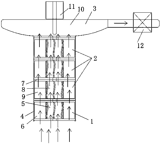
[0018] Such as figure 1 As shown, the structure of a multi-stage vane-free compressor with independent rotation and sequential acceleration of the present invention includes a first-stage compressor 1, a plurality of intermediate compressors 2 and last-stage compressors 3 stacked and connected in sequence, and the first-stage compressor 1 has the same structure as intermediate compressor 2. The air inlet of intermediate compressor 2 is sealed and connected with the outlet of first stage compressor 1, and the outlet of intermediate compressor 2 is sealed with the inlet of last stage compressor 3; first compressor 1 Including the first-stage housing 4, the first-stage motor 5 is arranged on the central axis of the first-stage housing 4, and the first-stage impeller 6 is arranged around the first-stage motor 5, and the first-stage impeller 6 is connected with the rotating end of the first-stage motor 5; The engine 2 includes an intermediate housing 7, an intermediate motor 8 is ar...


PUM


Abstract

The invention discloses a multistage stator-blade-free blade compressor structure capable of realizing independent rotation and successive acceleration, and belongs to the field of fluid compressors. The technical problem to be solved is to provide a kind of concentric and non-coaxial compressor structure without the need of static impellers and with multistage blades with different rotating speeds. According to the technical scheme for solving the technical problem, the multistage stator-blade-free blade compressor structure capable of realizing independent rotation and successive acceleration comprises a first stage compressor, a plurality of intermediate compressors overlaid and connected in sequence and a final stage compressor, the first stage compressor and the intermediate compressors are of the same structures, an air outlet of the first stage compressor is connected with air inlets of the intermediate compressors, and air outlets of the intermediate compressors are connected with an air inlet of the final stage compressor. The multistage stator-blade-free blade compressor structure can be widely applied in the field of fluid pressurization.

Description

Technical field [0001] The invention relates to a multi-stage vane compressor structure without stationary vanes independently rotating and sequentially accelerating, belonging to the technical field of fluid compressors. Background technique [0002] At present, common fluid compressors are mostly cylinder type, screw type, and impeller type compressor structures. Cylinder type and screw type compressors have large internal friction coefficients and generally need to use oil for lubrication, which has short service life and high noise. However, impeller type compression The machine is generally coaxially arranged with multi-stage impellers, so the impeller speed is the same when it is working, and static blades are installed between the impellers, through which the gas is retained, the density increases, the flow rate slows down, and the pressure increases. In the process of pressure increase, the internal temperature of the compressor will increase. In this coaxial multi-stage ...

Claims


Application Information

Patent Timeline
Patent Type & Authority Applications(China)
IPC IPC(8): F04D25/16F04D25/06F04D27/00
CPCF04D25/0606F04D25/16F04D27/003
Inventor 徐路统史英霞魏茂杰徐乔竹史珂刘淑文
Owner 山西方洁路路通净化技术有限公司
Why Eureka
Try Eureka