
Axial supporting device

A support device, axial technology, applied in the direction of bearings, ball bearings, bearing components, etc., can solve the problem of high tool cost, and achieve the effect of saving tool cost, reliable function, and avoiding self-locking

Inactive Publication Date: 2012-10-17
SCHAEFFLER TECH AG & CO KG
View PDF7 Cites 1 Cited by
  • Summary
  • Abstract
  • Description
  • Claims
  • Application Information

AI Technical Summary

Problems solved by technology

If two rolling bearings arranged radially offset are used, high tool costs arise because two different cages are required

Method used


Image

  • Axial supporting device
  • Axial supporting device

Examples


Embodiment Construction

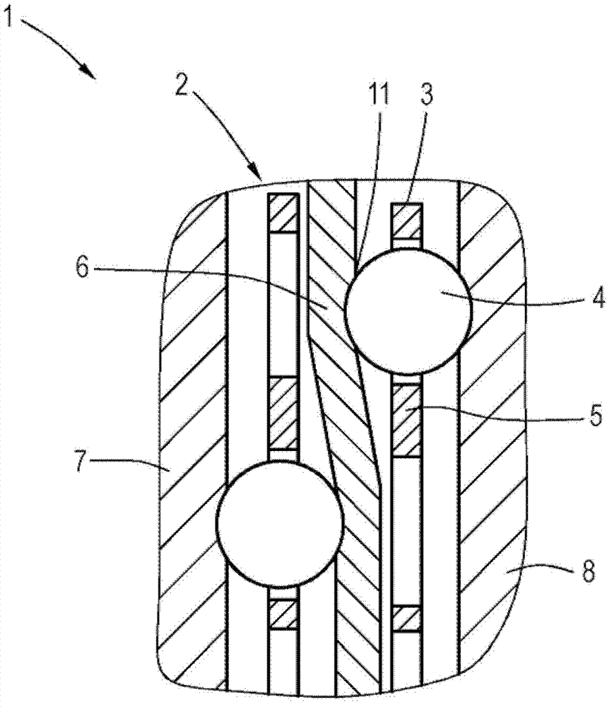
[0017] exist figure 1 The axial bearing 1 shown in the sectional side view of FIG. 2 comprises two rolling bearings 2 , 3 each having a rolling body 4 configured as a ball, which is accommodated in a cage 5 . The cage 5 is made of plastic material.

[0018] Roller bearings 2 , 3 are arranged parallel to one another with a component between them, which in the exemplary embodiment shown is designed as toothed segment 6 . The toothed segment 6 is a component part of an actuator for an electric axle of a vehicle. This electric axle includes a transmission, which is switched between two transmission stages by actuating an actuator. The toothed segment 6 is thus displaced axially during the shifting process.

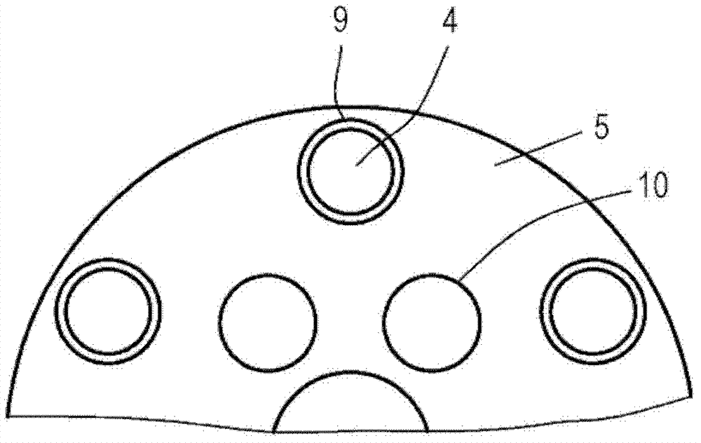
[0019] The rolling bodies 4 of the two rolling bearings 2 , 3 are each supported on the outer sides on raceways 7 , 8 . as best in the figure 2 As can be seen in the side view of , the cage 5 has a first opening 9 for a first (outer) pitch circle and a second opening 10 ...


PUM


Abstract

The axial supporting device (1) which is preferably used for a circular or disk-shaped component has a roller bearing (2) arranged on a side of the component and another roller bearing (3) arranged on the opposite side of the component. The roller bearings (2,3) are provided with different pitch circles and identical cages (5) which are provided openings (9,10) for the same pitch circles. The axial supporting device has a small axial space requirement, and can be manufactured at a low cost.

Description

technical field [0001] The invention relates to an axial bearing arrangement for a preferably annular or disk-shaped component comprising a first rolling bearing arranged on one side of the component and a second rolling bearing arranged on the opposite side of the component. Background technique [0002] A field of application for such an axial bearing is, for example, an electromechanical actuator with an actuator transmission via which the pinion is driven. The switching process of the actuator drive is triggered by the rotation of the pinion, which meshes with the gear or tooth segment. For this purpose, conventional bearing devices usually have a combination of two axial bearings, between which a toothing segment is accommodated, and a radial sliding bushing. The problem here, however, is that the radial sliding bushes require additional radial installation space, which is only available to a limited extent. This also creates the problem that the frictional relationsh...

Claims


Application Information

Patent Timeline
Patent Type & Authority Applications(China)
IPC IPC(8): F16C19/50F16C33/38F16C33/46F16C33/44F16C33/56
CPCF16C33/38F16C19/10F16C33/40F16C33/588
Inventor 托马斯·斯米塔那
Owner SCHAEFFLER TECH AG & CO KG
Learn More