Speed reducer and oil blocking cover thereof

A reducer and oil retaining cover technology, applied in the mechanical field, can solve problems such as reducing the life of lubricating oil, affecting the service life of the reducer, and reducing the viscosity of lubricating oil

Inactive Publication Date: 2012-10-17
WORLD TRANSMISSION TECH TIANJIN SHARE LTD
View PDF6 Cites 16 Cited by
  • Summary
  • Abstract
  • Description
  • Claims
  • Application Information

AI Technical Summary

Problems solved by technology

[0003] Obviously, when using oil-immersed lubrication, there should be enough lubricating oil in the reducer box to ensure the needs of lubrication, but the deeper the gear is immersed in the lubricating oil, the greater the degree of agitation of the lubricating oil when the gear rotates, that is The more work the gear does on the lubricating oil, the more the temperature of the lubricating oil rises, that is to say, the lower the thermal power of the reducer
[0004] Due to the high temperature of the lubricating oil, when the heat dissipation through the inner wall of the box is not enough to meet the heat dissipation of the lubricating oil of the reducer, the temperature of the lubricating oil will continue to be high, which will inevitably reduce the viscosity of the lubricating oil and make the lubricating oil easier to oxidize. In turn, the life of the lubricating oil is reduced and the frequency of oil change is increased, which affects the service life of the reducer

Method used


Image

  • Speed reducer and oil blocking cover thereof
  • Speed reducer and oil blocking cover thereof
  • Speed reducer and oil blocking cover thereof

Examples


Embodiment Construction

[0019] The purpose of the present invention is to provide a speed reducer, which can effectively control the temperature of lubricating oil during use, thereby increasing the thermal power.

[0020] The technical solutions in the embodiments of the present invention will be clearly and completely described below in conjunction with the accompanying drawings in the embodiments of the present invention. Obviously, the described embodiments are only some, not all, embodiments of the present invention. Based on the embodiments of the present invention, all other embodiments obtained by persons of ordinary skill in the art without making creative efforts belong to the protection scope of the present invention.

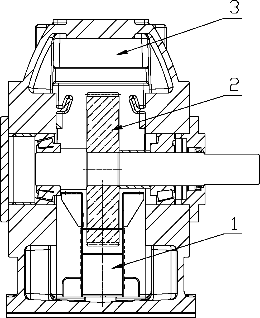
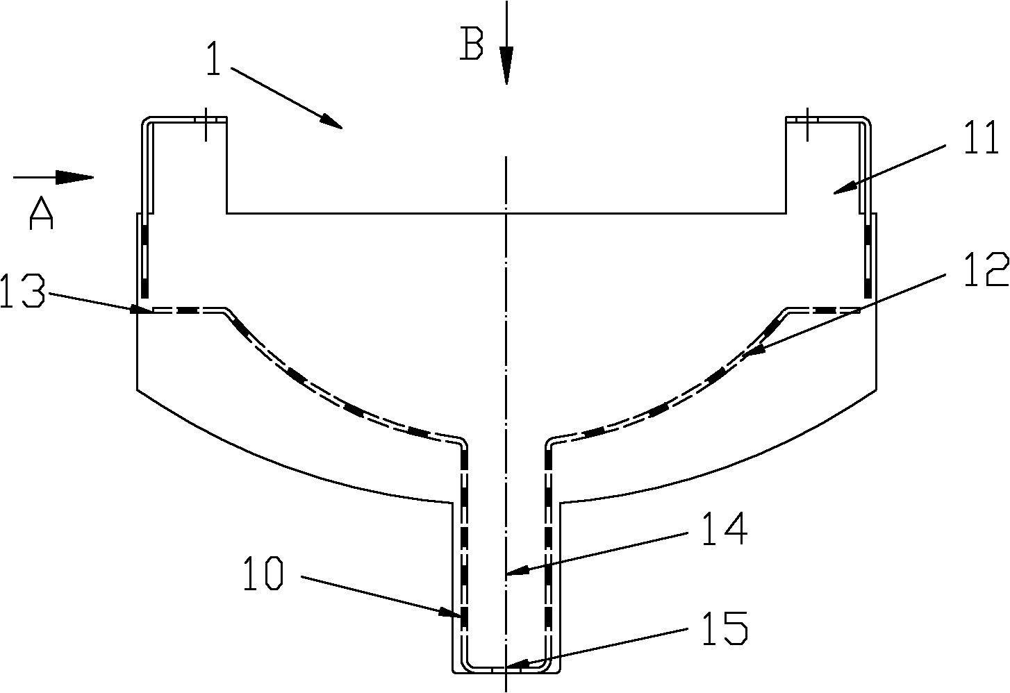
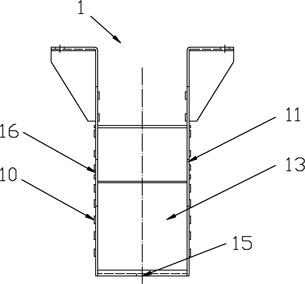
[0021] Such as figure 1 with figure 2 As shown, the speed reducer provided by the present invention includes an oil deflector 1 fixed inside the reducer casing 3. There is a gap between the lower part of the oil deflector 1 surrounding the gear 2 and the gear 2, and the o...


PUM


Abstract

The invention relates to the mechanical field, and in particular relates to a speed reducer. The speed reducer comprises an oil blocking cover fixed inside a box body of the speed reducer, wherein the oil blocking cover surrounds the lower portion of a gear, a gap is arranged between the oil blocking cover and the gear, and the oil blocking cover is provided with an oil inlet channel. When the speed reducer is in a work state, the gear can bring lubricating oil in the oil blocking cover to a region of engagement to conduct lubrication in a rotating process, friction heat in the region of engagement of the gear is brought to an oil pool so that temperature of the region of engagement of the gear is lowered, and the lubricating oil on the outside of the oil blocking cover can flow in the oil blocking cover continuously through the oil inlet channel so as to supplement the lubricating oil in the oil blocking cover. Simultaneously, the gear stirs the lubricating oil inside the oil blocking cover in the rotating process; namely, corresponding work is done on the lubricating oil inside the oil blocking cover. Due to the fact that the lubricating oil inside the oil blocking cover is less; namely, the lubricating oil stirred by the gear is less, so that the work done by the gear on the lubricating oil is less, temperature rise of the lubricating oil is less, and thermal power of the speed reducer is improved.

Description

technical field [0001] The invention relates to the field of machinery, and more specifically relates to a speed reducer and an oil shield thereof. Background technique [0002] A reducer is a transmission mechanism that uses gears and other transmission parts to transmit power. Among them, the transmission parts of the reducer need good lubrication, and most of the transmission parts of the reducer are lubricated with oil, and the lubrication method is mostly oil-immersed lubrication. Taking gears as an example, oil immersion lubrication is to immerse a part of the gear in lubricating oil. When the gears rotate, the lubricating oil sticking to them is brought to the meshing area for lubrication, so that an oil film is formed between the meshing tooth surfaces of the two gears. , so as to reduce the friction and improve the life of the gear; at the same time, the frictional heat will be introduced into the oil pool to eliminate the friction heat generated by the gear when t...

Claims


Application Information

Patent Timeline
Patent Type & Authority Applications(China)
IPC IPC(8): F16H57/04
Inventor 胡炜
Owner WORLD TRANSMISSION TECH TIANJIN SHARE LTD
Why Eureka
Try Eureka