Reaction system for synthesizing silicon nitride powder

A reaction system, silicon nitride powder technology, applied in nitrogen compounds, chemical/physical/physical chemistry nozzle reactors, inorganic chemistry, etc. The effect of long time, smooth metal surface and high thermal power

Active Publication Date: 2018-10-09
ZHEJIANG YUYAO NEW MATERIAL CO LTD
View PDF5 Cites 4 Cited by
  • Summary
  • Abstract
  • Description
  • Claims
  • Application Information

AI Technical Summary

Problems solved by technology

[0015] 4. Difficult production management: many equipment, large workshop, many links, many processes, large investment
[0016] 5. Many supporting facilities: auxiliary facilities such as dust absorption, anti-static, vibration isolation, and noise reduction

Method used


Image

  • Reaction system for synthesizing silicon nitride powder
  • Reaction system for synthesizing silicon nitride powder
  • Reaction system for synthesizing silicon nitride powder

Examples


Embodiment 1

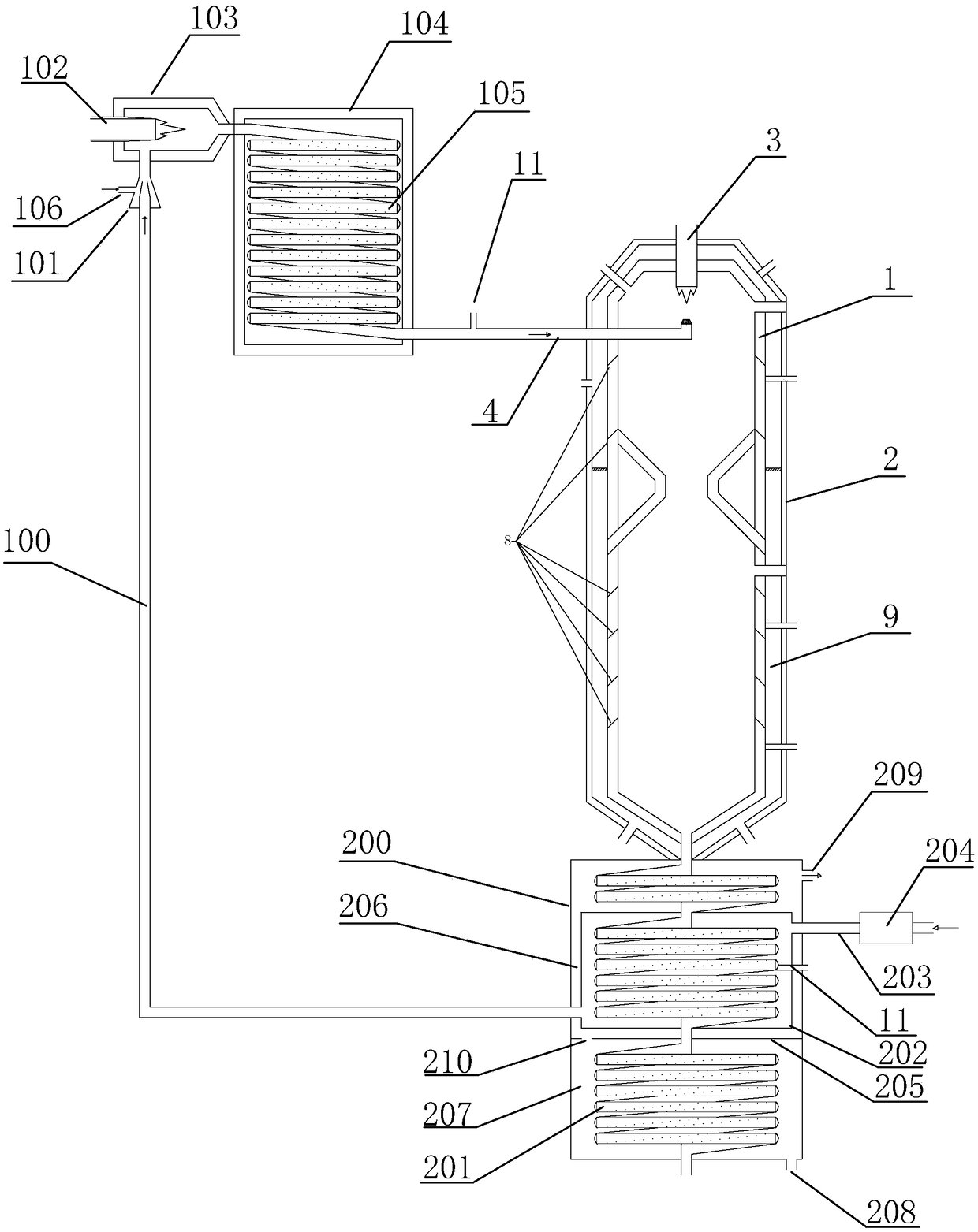
[0080] Such as figure 1 As shown, a reaction system for synthesizing silicon nitride powder includes a microwave plasma preheater, a suspension reactor and an insulation cooler connected in sequence.

[0081] The microwave plasma preheater includes a nitrogen pipeline 100 , a first injector 101 , a microwave plasma torch 102 (ceramic material), a second injector 103 , a preheater shell 104 and a coil 105 . The first injector is provided with a silicon powder addition port 106, the discharge end of the nitrogen pipeline extends into the first injector, the discharge end of the first injector is connected with the second injector, and the first injector The pressure inside is less than the pressure inside the second injector. The microwave plasma torch is arranged in the second injector; the coil is arranged in the shell of the preheater, and the discharge end of the second injector is connected with the feed end of the coil, and the shell of the preheater is connected with the...

Embodiment 2

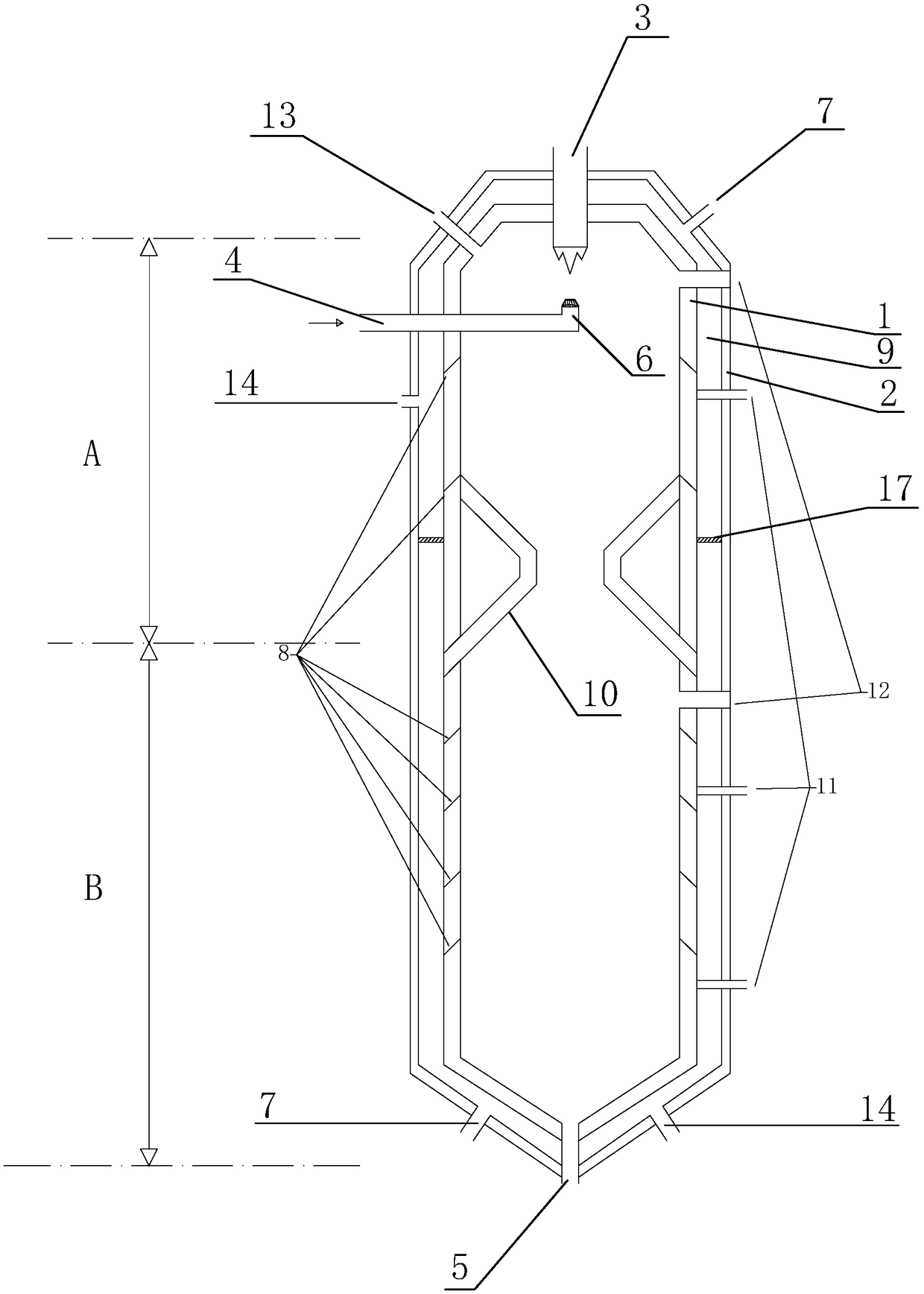
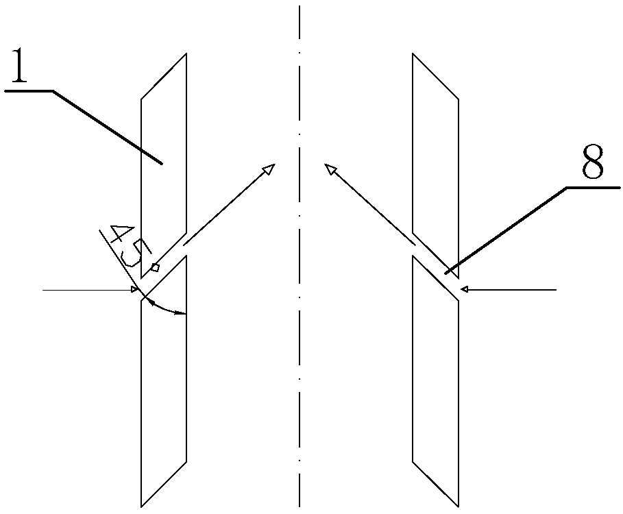
[0088] The difference between this embodiment and Embodiment 1 is that: the vertical angle of the air inlet slit is 30 degrees. And the air inlet slots are respectively provided with 1 layer and 5 layers in the heating area and the reaction area.

Embodiment 3

[0090] The difference between this embodiment and Embodiment 1 is that: the vertical angle of the air inlet slit is 50 degrees. And the air inlet slots are respectively provided with 1 layer and 3 layers in the heating zone and the reaction zone.

[0091] Reactor production of the present invention compares with main index in the industry

[0092] index


PUM


Abstract

The invention relates to the field of silicon nitride preparation, and discloses a reaction system for synthesizing silicon nitride powder. The reaction system comprises a microwave plasma preheater,a suspension reactor and a heat insulation cooler, wherein the suspension reactor comprises a furnace tube, a furnace case, a heating torch and a spray pipe; an inner cavity of the furnace pipe is divided into a heating region and a reaction region; the upper end of the furnace pipe is fixedly provided with the heating torch; the lower end of the furnace pipe is provided with a discharging opening; the furnace case is sleeved outside the furnace pipe; heat insulation cotton is arranged between the furnace pipe and the furnace case; the spray pipe penetrates through the furnace case and the furnace pipe to enter the heating region of the inner cavity of the furnace pipe; in addition, a spray nozzle is arranged at the tail end of the spray pipe; a nitrogen gas inlet is formed in the furnacecase; a circle of air inlet seam is arranged at the same height on the inner wall of the furnace pipe; the air inlet seam is provided with an opening in the vertical direction and is in an inclined upward direction towards the inner cavity of the furnace pipe; the air inlet seam is provided with an opening in the horizontal plane, is approximately or completely tangent with the curve surface of the inner wall of the furnace pipe; in addition, the facing directions of all openings are identical. The silicon nitride powder prepared by the reaction system has the advantages of high purity, fine particle diameter, high alpha phase content, high yield and fast production.

Description

technical field [0001] The invention relates to the field of silicon nitride preparation, in particular to a reaction system for synthesizing silicon nitride powder. Background technique [0002] Silicon nitride is an important structural ceramic material. It is a superhard substance, inherently lubricious, and wear-resistant, and is an atomic crystal; it resists oxidation at high temperatures. Moreover, it can also resist cold and heat shocks, and it will not shatter when heated to above 1000°C in the air, cooled rapidly and heated again sharply. It is precisely because silicon nitride ceramics have such excellent characteristics that people often use it to manufacture mechanical components such as bearings, gas turbine blades, mechanical seal rings, and permanent molds. [0003] At present, domestic silicon nitride powder production mainly consists of the following two methods: [0004] 1. Bell furnace electric or microwave heating nitrogen infiltration method [0005]...

Claims


Application Information

Patent Timeline
IPC IPC(8): C01B21/068B01J19/00B01J19/26
CPCB01J19/0053B01J19/26C01B21/0682C01P2006/80Y02P20/141
Inventor 任小平
Owner ZHEJIANG YUYAO NEW MATERIAL CO LTD
Why Eureka
Try Eureka